About Class 10 Physics Notes & Questions – Magnetism
The chapter Magnetic Effects of Electric Current explains how current produces magnetism and its applications in daily life. This is a conceptual and practical chapter with diagrams and experiments.
It was seen that certain ores could attract bits of iron and they always pointed in a particular direction when suspended freely. These ores were named as magnetite. This property of attracting small pieces of iron is referred to as magnetism. Therefore, a magnet is a substance, which has both attractive and directive properties. Magnet is also known as lodestone and it is chemically the oxide of iron (fe3o4).
Types of magnets
Magnets are of two types:
Natural magnets
They are weak and mostly irregular in shape.
Artificial magnets
When natural magnets are rubbed against iron or steel bars, the same property of attraction is communicated to these bars. They can be strong and have any desired shape and size.
Types of artificial magnets
- Bar magnets: they may be cylindrical or rectangular in shape.
- Magnetic needle: it is in the form of an elongated rhombus. The pole regions almost contract to the points at the ends of the needle while the remaining region is a neutral zone. The magnetic needle is either pivoted to a nail or suspended so that it can rotate freely.
- Magnetic compass: it is a compact form of magnetic needle, which is pivoted at the center of a small box, made of brass having a glass top. The north pole of this needle is generally painted red.
Use of magnetic compass
- to check the polarity of a magnet.
- to find the direction of magnetic field.
- to find the magnetic north-south direction.
Magnetic field and magnetic field lines
All magnets have a space around them in which the force of attraction and repulsion can be detected. This space is known asmagnetic field. We can describe the magnetic field around a magnet by magnetic field lines. These are the curved paths along which magnetic force is acting on them in the magnetic field of the bar magnet. These lines are called magnetic lines of forces.
Magnetic field lines
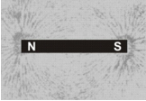
To know the magnetic lines of forces, place a magnet on a cardboard sheet and gently sprinkle some iron filings uniformly over it. The iron filings are found to arrange themselves in a pattern.
Tracing magnetic field lines of a bar magnet using a magnetic compass
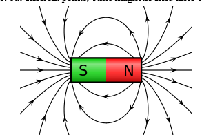
Take a paper sheet and fix it on a drawing board by pins. Place a bar magnet and mark its boundary. Now place a small compass needle close to south pole of the magnet and mark two pencil dots at two ends of the needle. Now move the compass in such a manner that one end (n) of the needle coincides with the second pencil dot. Mark the position of the other end(s) with a dot. Repeat this process of moving the needle and marking dots at its two ends till its south pole reaches the north pole of the magnet. Get a smooth curve by joining the dots. This smooth curve represents a magnetic field line. By repeating the above process from the same pole of the magnet but different points, other magnetic field lines can be traced.
Properties of magnetic field lines
- a magnetic field line is a closed and continuous curve.
- a magnetic field line is directed from north pole to south pole outside the magnet. Whereas inside the magnet, the field lines are directed from south pole to north pole.
- the magnetic field lines are crowded near the pole where the magnetic field is strong and are far apart near the middle of the magnet and far from the magnet where the magnetic field is weak.
- the magnetic field lines never intersect each other because if they do so, these would be two directions of magnetic field at that point, which is not possible.
- in case the field lines are parallel and equidistant, these represent a uniform magnetic field. The earth's magnetic field is uniform in a limited space.
Magnetic effect of current
Hans oersted, in 1820, first discovered that when an electric current is passed through a conducting wire, a magnetic field is produced around it. If a compass needle is kept in the vicinity of the current carrying wire, the needle is found to deflect in a definite direction. If the direction of current in the wire is reversed, then the direction of deflection of the needle is reversed.
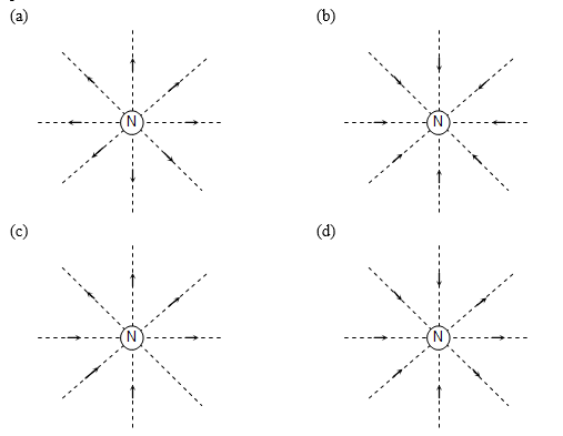
Ab is a wire lying in the north-south direction and connected to a battery through a rheostat and a tapping key. A compass needle is kept just below the wire. When the key is open I.E. No current is passed through the wire, the needle shows no deflection and points in the n-s direction (I.E. Remains parallel to the wire) as shown in figure(a)
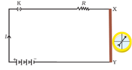
When the key is pressed and a current passes in the wire in the direction a to b (I.E. From south to north) and the north pole (n) of the needle deflects towards the west as figure(b). Thus, a current (or moving charge) produces a magnetic field. When the direction of current in the wire is reversed by reversing the terminals of the battery, the north pole of the needle deflects towards the east as figure(c).
Ampere's swimming rule
Let the observer imagine himself to be swimming along the conductor in the direction of the current and facing the magnetic needle, then the north pole of the needle will be deflected towards his left hand.
Magnetic field due to a straight current carrying wire
When a current is passed through a conducting wire, a magnetic field is produced around it. The direction of magnetic field due to a straight current carrying wire can be mapped by means of a small compass needle or by iron filings.
Take a sheet of smooth cardboard with a hole at the centre. Place it horizontally and pass a wire vertically through the hole.Sprinkle some iron filings on the cardboard and pass an electric current through the wire. Gently tap the cardboard. We find that the iron filings arrange themselves in concentric circles around the wire as shown in figure.
If a small compass needle is kept anywhere on the board near the wire, the direction in which the north pole of the needle points gives the direction of the magnetic field (I.E., magnetic lines of force) at that point.
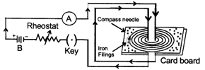
The magnetic lines of force form concentric circles near the wire, with their plane perpendicular to the straight conductor and with their centres lying on its axis. If the direction of current in the wire is reversed, the direction of lines of force is also reversed.
On increasing the strength of current in the wire, the lines of force becomes denser and iron filings are arranged in circles upto a larger distance from the wire, showing that the magnetic field strength has increased.
Magnitude (b) of magnetic field
- If the current (I) in the conductor xy is increased, the deflection of the needle of the compass (used for mapping the field) also increased. Since deflection of the compass is a measure of b, it is clear that magnetic field (b), increases with the increase in current (I), I.E.,
BµI ... (I)
- If the distance (r) of the compass from the conductor is increased, the deflection of the needle decreases, I.E., ... (ii)
- Combing (I) and (ii), we get ... (iii)
Then,
B = magnetic field strength , m0 = permeability of vacuum (a constant)
I = current (flowing in conductor) and
R = distance from the conductor (where magnetic field is measured).
Do Check: Human Eye and Colourful World Class 10 Notes
Unit of magnetic field
When current (I) is measured in ampere (a) and distance (r) in metre (m), magnetic field (b) is expressed in a unit named tesla (t).
Direction of magnetic field
The direction of magnetic field (lines of force) produced due to flow of current can be known by the following rules:
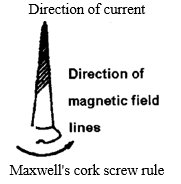
Maxwell's cork screw rule
Imagine a right handed cork screw lying with its axis coincides with the current carrying wire. It is now rotated such that it advances in the direction of the current, the direction in which the screw rotates gives the direction of the magnetic lines of force.
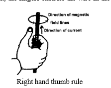
Right hand thumb rule
If we hold the current carrying conductor in the right hand such that the thumb points in the direction of current, the fingers encircle the wire in the direction of magnetic lines of force.
Magnetic field due to circular coil carrying current
A piece of wire bent in the form of a ring (or coil) is passed through a horizontal cardboard c at two points p and q at the opposite ends of a diameter of the ring and then some iron filings are scattered on the cardboard. The ends of the coil are connected to a battery through a rheostat and a key. When a strong electric current is passed through the coil by closing the key and the cardboard is gently tapped we find that the iron filings arrange themselves in a definite pattern representing the magnetic lines of force due to the current carrying coil.
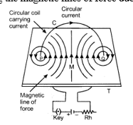
Direction of magnetic field is found by applying the right hand thumb rule to each section of the coil and we find that the concentric lines of force pass through the coil in the same direction. Further note that:
- The magnetic lines of force are nearly circular near the wire.
- Within the space enclosed by the wire, the lines of force are in the same direction.
- Near the centre of the coil, the lines of force are nearly parallel and the magnetic field may be assumed to be practically uniform for a small space around the centre.
- At the centre, the lines of force are along its axis and at right angle to the plane of the coil.
- The magnetic field strength is increased if the number of turns in the coil are increased or the strength of current in the coil is increased.
Since the magnetic lines of force through the coil point in the same direction, hence one face of the coil acts as a large area of north polarity because it is sending out magnetic lines of force and the other face acts as a large area of south polarity as magnetic lines of force are entering it. Thus, the coil has a magnetic field similar to a magnetised iron disc of same radius as that of the coil.
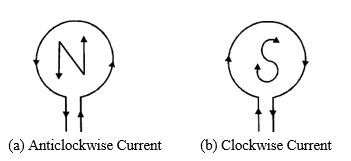
The polarity of the faces of the coil depends on the direction of current and is determined by the clock rule. Looking at the face of the coil, if the current around that face is in an anticlockwise direction, the face has north polartiy while if the current at that face is in the clockwise direction, the face has south polarity. This can be tested by using a compass needle.
The magnitude of the magnetic field (b) at the centre of the coil is
- Directly proportional to the current (I) flowing through it, I.E., BµI ... (I)
- Inversely proportional to the radius (r) of the coil, I.E., ... (ii)
- Directly proportional to the total number of turns (n) in the coil, I.E., Bµn ... (iii)
This is due to the reason that the current in all the circular turns of the coil is in the same direction. As such, the resultant magnetic field due to the coil is equal to the sum of the fields due to all these turns.
Combining (I), (ii) and (iii), we obtain ... (iv)
Magnetic field produced by a circular coil carrying current is directly proportional to both, number of turns (n) and current (I), but inversely proportional to its radius (r). Thus, the strength of magnetic field produced by a current carrying circular coil can be increased by
- Increasing the number of turns of wire in the coil,
- Increasing the current flowing through the coil and
- Decreasing the radius of the coil.
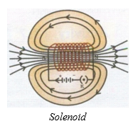
Magnetic field due to a current-carrying solenoid
An insulated copper wire wound on a cylindrical cardboard (or plastic) tube such that its length is greater than its diameter is called a solenoid. The solenoid is from greek word for “channel”.
To obtain the pattern of magnetic field due to a solenoid, cut a slit in a hard cardboard in such a way that the length of the slit is equal to the length of the solenoid and the width of the slit is equal to the diameter of the solenoid. Fix the solenoid (ab) in the slit in such a manner that the axis of the solenoid is in the plane of the cardboard. The ends of the solenoid are connected to a battery through a rheostat (rh) and a key (k). Sprinkle iron filings on the board after passing current through the solenoid. On tapping the board, the iron filings arrange themselves in the pattern similar to one shown in figure. The magnetic field lines can also be mapped with the help of a compass needle. The arrows on the field lines are marked in the direction in which the north pole of the compass needle points, as shown in the figure.
Conclusions
- The magnetic field lines inside the solenoid are nearly straight and parallel to its axis. Thus, the magnetic field inside a solenoid is uniform.
- The magnetic field lines are exactly identical to those due to a cylindrical bar magnet with one end of the solenoid acting as a south pole and its other end acting as a north-pole. Thus, a current-carrying solenoid behaves like a bar magnet with fixed polarities at its ends.
As a result of this:
- A current-carrying solenoid, when freely suspended, sets itself in the north south direction exactly in the same manner as a bar magnet does I.E. It acquires the directive property of a bar magnet.
- A current-carrying solenoid acquires the attractive property of a bar magnet. As such, iron filings are attracted to it when these are brought near it.
Direction of magnetic field
The end of the current-carrying solenoid at which the current flows anticlockwise behaves as a north pole while that end at which the direction of current is clockwise behaves as a south pole as shown in figure. This is according to the clock rule, which has earlier been stated.
Magnitude of magnetic field (b)
The magnitude of the magnetic field inside the solenoid is
- Directly proportional to the current (I) flowing through the solenoid, I.E., BµI ... (I)
- Directly proportional to the number of turns per unit length of the solenoid (n) and not on the total number of turns on the solenoid, I.E. B μ n ... (ii)
Combining (I) and (ii),
Bµni ... (iii)
Or
Electromagnets and permanent magnet
Electromagnet
An electromagnet is a temporary strong magnet and is just as a solenoid with its winding on a soft iron core.
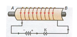
An electromagnet consists of a soft iron core ab placed inside a solenoid. The current in the solenoid can be adjusted with a rheostat rh in the circuit having a battery and a key, k as shown in figure. An electromagnet acquires the magnetic properties only when an electric current is passed through the solenoid. Once the current is switched off, it almost loses its magnetic properties as the retentivity (the ability to retain magnetism) of soft iron is very low.
The strength of the electromagnet depends upon:
- Amount of current flowing.
- Number of the circular turns of wire.
In order to provide a strong magnetic field in a small region, an electromagnet is made in the u-shape. Such a magnet is called a horse-shoe magnet.
Uses of electromagnets
Electromagnets are used in electrical devices such as an electric bell, an electric fan, telegraph, an electric train, an electric motor, generator etc.
For lifting and transporting large masses of iron in the form of girders.
In medical practice, for removing pieces of iron from wounds.
Permanent magnet
A permanent magnet is made from steel. As steel has more retentivity than iron, it does not lose its magnetism easily.
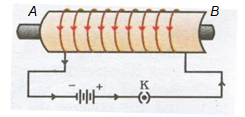
A steel bar is placed inside a solenoid ab as shown in the figure and the current is switched on and off with help of key k. On removing and testing the bar, it is found to be magnetised. It is of no use to pass the current through the solenoid for a long time because the bar will not be magnetised beyond a certain limit. On the other hand, the solenoid may be damaged due to overheating.
Apart from different varieties of steel (carbon steel, chromium steel, cobalt and tungsten steel), some alloys like alnico (aluminium, nickel and cobalt) and nipermag (an alloy of iron, nickel, aluminum and titanium) are used to make very strong permanent magnets.
Uses of permanent magnets
Permanent magnets are used in
- Electric meters (galvanometers, voltmeters, ammeters, speedometers etc.)
- Microphones and loudspeakers and
- Electric clocks.
Difference between a bar magnet (for permanent magnet) and an electromagnet:
TABLE
Permanent magnets are usually made of alloys such as carbon-steel, chromium-steel, cobalt-steel, tungsten-steel, nipermag and alnico. Nipermag is an alloy of iron, nickel, aluminium and titanium whereas alnico is an alloy of aluminium, nickel and cobalt . Permanent magnets of these alloys are much more stronger than those made of ordinary steel, such strong permanent magnets are used in microphones, loudspeakers, electric clocks, ammeters, voltmeters, speedometers and many other devices.
Methods of demagnetising a permanent magnet
Magnet can be demagnetised by:
- Self-demagnetisation, if the magnet is stored without using magnetic keepers.
- Dropping it from a height or by rough handling.
- Heating or hammering the magnet.
Magnet can be demagnetised by placing it within a solenoid and passing high frequency ac through it.
Uses of magnetism in medicine
An electric current always produces a magnetic field. Even weak ion currents that travel along the nerve cells in our body produce magnetic fields.
When we touch something, our nerves carry an electric impulse to the muscles we need to use. The impulse produces a temporary magnetic field. These fields are very weak and are one billionth of the earth's magnetic field. Heart and brain are the two main organs in the human body where the magnetic field produced is significant. The magnetic field inside the body forms the base of obtaining the images of different body parts. This is done by using a technique called magnetic resonance images (mri). Analysis of these images helps in medical diagnosis. Magnetism has thus, got important uses in medicine.
Magnetic force
Force on a current-carrying conductor in a magnetic field
Immediately after oersted's discovery of electric currents producing magnetic fields and exerting forces on magnets, ampere suggested that magnet must also exert equal and opposite force on a current-carrying conductor. When a current carrying conductor is kept in a magnetic field (not parallel to it), a force acts on it. This force is created due to the interaction of magnetic field of the current in the conductor and the external magnetic field on the conductor. As a result of this superposition, the resultant magnetic field on one side of conductor is weaker than on the other side. Hence the conductor experiences a resultant force in one direction.
Take a small aluminium rod ab. Suspend it horizontally by means of two connecting wires from a stand. Now, place a strong horseshoe magnet in such a way that the rod is between the two poles with the field directed upwards. If a current is now passed in the rod from b to a, we will observe that the rod gets displaced. This displacement is caused by the force acting on the current-carrying rod. The magnet exerts a force on the rod directed towards the right, with the result the rod will get deflected to the right. If we reverse the current or interchange the poles of the magnet, the deflection of the rod will reverse, indicating thereby that the direction of the force acting on it gets reversed. This shows that there is a relationship among the directions of the current, the field and the motion of the conductor.
Direction of force on current carrying conductor
The direction of force is obtained by the fleming's left hand rule.
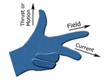
Fleming's left hand rule
Stretch the forefinger, middle finger and the thumb of your left hand mutually perpendicular to each other as shown in figure. If the forefinger indicates the direction of the magnetic field and the middle finger indicates the direction of current, then the thumb will indicate the direction of motion (I.E., force) on the conductor.
Magnitude of force
Experimentally it is found that the magnitude of the force acting on a current carrying conductor kept in a magnetic field in direction perpendicular to it, depends on the following factors :
- The force f is directly proportional to the current flowing in the conductor, I.E. F a l.
- The force f is directly proportional to the intensity of magnetic field, I.E. F a b.
- The force f is directly proportional to the length of the conductor (inside the magnetic field), I.E. Fa l.
Combining these we get, f = ibi or f = k I b l
Where k is constant whose value depends on the choice of units. In s.I. Units k = 1 and the unit of magnetic field is tesla (t). 1 tesla is equal to 1 newton ampere-1 metre-1 or 1 weber metre-2.
Force is directly proportional to sinθ where a is the angle between current and the direction of magnetic field. I.E., f a sinq
Combining all we have f = bil sinq or
Special cases:
- When q = 00 or 1800, sinq = 0 þ f = 0
Force on a current - carrying conductor placed parallel or antiparallel to magnetic field is zero.
- If q = 90°, sin q =sin 90° = 1, f= bil is the maximum force. Force experienced by the conductor is maximum when placed perpendicular to magnetic field.
- If b = 0, f = 0 I.E. The coil placed in field free area doesn't experience any force.
A moving charge in a magnetic field (direction of motion not parallel to the field direction) experiences a force called lorentz force. Since current is due to flow of charge, therefore a conductor carrying current will experience a force.
The force acting on a current-carrying conductor placed in a magnetic field is: f=bil
Now, if a charge q flows in time t then the current I = . So, writing in place of I in the above equation, we get:
Suppose the particle carrying the charge q travels a length l in time t. Then the velocity v of the charged particle will be equal to . Writing v in place of in the above equation, we get:
Force on moving charge, f = b x q x v
Where b = magnitude of magnetic field, q = charge on the moving particle and v = velocity of the charged particle (in metre per second). In vector notation
When an electric current is passed through a conductor, a magnetic field is produced around the conductor. Faraday thought that as a magnetic field is produced by electric current, it should be possible to produce an electric current by the magnetic field. According to him, whenever there is a change in the magnetic lines of force associated with a conductor, an electromotive force (e.M.F.) is set up at the ends of the conductor which lasts as long as the change is taking place. This phenomenon is called electromagnetic induction.
Force acting on a charge moving a magnetic field
We have just learnt that a current-carrying conductor experiences a force when placed in a magnetic field. But we know that current is due to charges in motion. Thus, it is clear that a charge moving in a magnetic field experiences a force, except when it is moving in a direction parallel to it.
Direction of force
Since the direction of current is the same as that of the motion of a positive charge, the direction of force acting on it, when moving perpendicular to direction of magnetic field, is the same as that acting on a current-carrying conductor placed perpendicular to the direction of magnetic field. The direction of force is given by fleming's left-hand rule. Obviously, the force acting on a negative charge moving in a direction perpendicular to the magnetic field is opposite to that acting on a positive charge.
Characteristics of magnetic force
- Magnetic force acts only on moving charges and not on stationary charges.
- No magnetic force acts on a charge if it is moving along the direction of the magnetic field.
- The direction of magnetic force is perpendicular to
- The direction of velocity of the charge and
- The direction of the magnetic field.
- The magnetic force (f) depends on the charge (q), velocity (v) and the strength (b) of the magnetic field I.E. F = q v b (in case the direction of v is perpendicular to the direction of b).
- The magnetic force (f) acting on a current-carrying conductor placed perpendicular to the direction of magnetic field (b) is given by f = l l b.
Where I is the current flowing in the conductor, l is its length in the magnetic field.
Faraday's experiments
Wind an insulated copper wire on a wooden cylinder so as to form a solenoid coil. Connect the two ends of the coil to the centre of galvanometer. A magnet is placed along the axis of the coil.
- When the magnet is stationary, there is no deflection in the galvanometer. The pointer reads zero as shown in figure (a).
- When the north pole of the magnet is brought near the coil, the current flows in the coil in left direction shown in the figure (b) and the galvanometer shows the deflection towards the right.
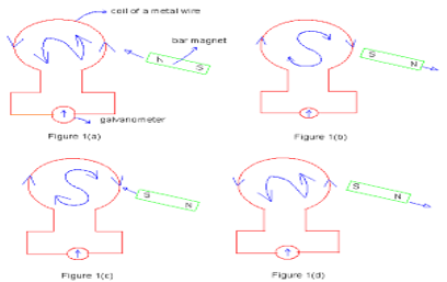
- If we stop the motion of the magnet, the pointer of the galvanometer comes to the zero position as shown in figure (c). Thus the current in the coil flows so long as the magnet is moving. If the magnet is taken away from the coil, the current again flows in the coil but in the direction opposite to that shown in figure (d) and therefore the pointer of the galvanometer deflects towards the leftside.
- If south pole of the magnet is brought towards the coil, the current in the coil flows in the direction opposite to that shown in figure (e) and so the pointer of the galvanometer deflects towards the left.
- Similar deflection is observed in the galvanometer if the magnet is kept stationary and the coil is moved.
From this experiment faraday concluded that:
- The galvanometer shows a deflection (I.E. Current flow in the coil) only when there is a relative motion between the coil and the magnet.
- The direction of deflection is reversed if the direction of motion is reversed.
- The value of the current in the coil (I.E. Deflection of the pointer) is increased by:
- The rapid motion of the magnet or the coil.
- The use of a strong magnet.
- Increasing the area and number of turns in the coil.
When the magnet and coil are relatively at rest, the total number of magnetic lines of force due to the magnet passing through the coil (I.E. The magnetic flux linked with the coil) remains constant, therefore no e.M.F. Is induced in the coil and the galvanometer shows no deflection.
When there is relative motion between the coil and magnet, the magnetic flux linked with the coil changes. If the coil is moved towards the magnet, the magnetic flux through the coil increases.Due to change in magnetic flux linked with the coil, an e.M.F. Is induced in the coil. This e.M.F. Causes a current to flow if the circuit of the coil is closed.
Faraday's laws of electromagnetic induction
Faraday formulated the following two laws of electromagnetic induction:
Whenever there is a change in magnetic flux linked with a conductor, an e.M.F. Is induced. The induced e.M.F. Lasts so long as there is a change in magnetic flux cut by the conductor.
The magnitude of the e.M.F. Induced is directly proportional to the rate of change of magnetic flux cut by the conductor. If the rate of change of magnetic flux remains uniform, a steady e.M.F. Is induced. If the circuit of conductor is closed, a current flows in the conductor due to the e.M.F. Induced across its ends.
Direction of induced E.M.F:
The direction of induced e.M.F. (and hence the direction of induced current) can be obtained by any or the following rules:
- Fleming's right hand rule
- Lenz's law
Fleming's right hand rule
Stretch the thumb, middle finger and the forefinger of your right hand mutually perpendicular to each other as shown in figure. If the forefinger indicates the direction of the magnetic field and the thumb indicates the direction of motion of the conductor, then the middle finger will indicate the direction of induced current.
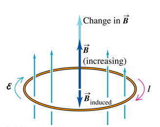
Lenz's law
This law gives us the direction of current induced in a circuit. According to lenz's law, the induced current will appear in such a direction that it opposes the change (in magnetic flux) responsible for its production.
The law refers to induced currents, which means that it applies only to closed circuits. If the circuit is open, we would find the direction of induced e.M.F. For example, in figure, when the magnet is moved towards the loop, a current is induced in the loop. The induced current produces its own magnetic field with magnetic dipole moment oriented so as to oppose the motion of the magnet. Thus the induced current must be anticlockwise as shown in figure below.
Electric generators
A generator or dynamo is a machine used for generating electric current by converting mechanical energy into electrical energy. Generators are of two types depending upon the type of current they produce.
It is of two types :
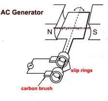
Ac generator or dynamo
When a coil (conductor) is rotated in a magnetic field, the magnetic flux linked with it changes and therefore an alternating e.M.F. Is induced in the coil.
Construction: the main parts of a dynamo are:
- Field magnet: it is a strong horse shoe permanent magnet. An electromagnet run by a dc source can also be used for high power generators.
- Armature: it is a soft iron core on which a coil abcd having a large number of turns of insulated copper wire is wound. This armature (or coil) is rotated rapidly in the magnetic field between the poles of the magnet.
- Slip rings: the ends of the armature (or the coil) are connected to two coaxial metallic slip rings s1 and s2 which rotate along with the coil.
- Brushes: two brushes b1 and b2 made of carbon, press against the slip rings s1 and s2 respectively the external circuit (I.E. Load) is connected between the other ends of brushes. The brushes b1 and b2 do not rotate along with the coil.
Working of an AC generator
Suppose that the generator coil abcd is initially in the horizontal position. Again suppose that the coil abcd is being rotated in the anticlockwise direction between the poles n and s of a horse-shoe type magnet.
- As the coil rotates in the anticlockwise direction, the side ab of the coil moves down cutting the magnetic lines of force near the n - pole of the magnet and side cd moves up, cutting the lines of force near the s-pole of the magnet. Due to this, induced current is produced in the sides ab and dc of the coil. On applying fleming's right-hand rule to the sides ab and dc of the coil, we find that the currents are in the directions b to a and d to c. Thus, the induced currents in the two sides of the coil are in the same direction and we get an effective induced current in the direction badc.
- After half revolution, the sides ab and dc of the coil will interchange their positions. The side ab will come on the right hand side and side dc will come on the left hand side. So, after half a revolution, side ab starts moving up and side dc starts moving down. As a result of this, the direction of induced current in each side of the coil is reversed after half a revolution. Since the direction of induced current in the coil is reversed after half revolution so that polarity (positive and negative) of the two ends of the coil also changes after half revolution. The end of coil which was positive in the first half of rotation becomes negative in the second half. And the end which was negative in the first-half revolution becomes positive in the second half of revolution. Thus, in 1 revolution of the coil, the current changes its direction 2 times.
The alternating current (ac ) produced in india has a frequency of 50 hz. That is, the coil is rotated at the rate of 50 revolutions per second. Since in 1 revolution of coil, the current changes its direction 2 times, so in 50 revolutions of coil, the current changes its direction 2 x 50 = 100 times. Thus, the ac supply in india changes its direction 100 times in 1 second. Another way of saying this is that the alternating current produced in india changes its direction every 11100 second. That is, each terminal of the coil is positive(+) for 1/100 of a second and negative (-) for the next 1/100 of a second.
Dc generator (or dc dynamo)
"Dc generator" means "Direct current generator". That is, a dc generator produces direct current.
Construction of a dc generator
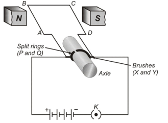
A simple dc generator consists of a rectangular coil abcd which can be rotated rapidly between the poles north and south of a strong horse-shoe type magnet m.
The generator coil is made of a large number of turns of insulated copper wire. The two ends of the coil are connected to the two copper half rings (or split rings) r1 and r2 of a commutator. There are two carbon brushes b1 and b2 which press lightly against the two half rings. When the coil is rotated, the two half rings r1 and r2 touch the two carbon brushes b1 and b2 one by one. So, the current produced in the rotating coil can be tapped out through the commutator half rings into the carbon brushes. From the carbon brushes b1 and b2, we can take the current into the various electrical appliances like radio, tv, electric iron, bulbs, etc.
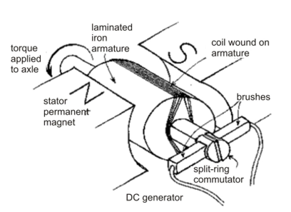
Working of a DC generator:
Suppose that the generator coil abcd is initially in the horizontal position. Again suppose that the coil abcd is being rotated in the anticlockwise direction between the poles n and s of a horse-shoe type magnet.
- As the coil rotates in the anticlockwise direction, the side ab of the coil moves down cutting the magnetic lines of force near the n-pole of the magnet and side dc moves up, cutting the lines of force near the s-pole of the magnet in figure. Due to this, induced current is produced in the sides ab and dc of the coil. On applying fleming's right-hand rule to the sides ab and dc of the coil we find that the currents in them are in the directions b to a and d to c respectively. Thus, we get an effective induced current in the direction badc. Due to this the brush b1 becomes a positive (+) pole and brush b2 becomes negative (-) pole of the generator.
- After half revolution the sides ab and dc of the coil will interchange their positions. The side ab will come on the right hand side and start moving up whereas side dc will come on the left-hand side and start moving down. But when sides of the coil interchange their positions, then the two commutator half rings r1 and r2 automatically change their contacts from one carbon brush to the other. Due to this change, the current keeps flowing in the same direction in the circuit. The brush b1 will always remain positive terminal and brush b2 will always remain negative terminal of the generator. Thus, a dc generator supplies a current in one direction by the use of a commutator consisting of two half-rings of copper.
Difference between a DC generator and an AC generator:
In a dc generator we connect the two ends of the coil to a commutator consisting of two, half rings of copper. On the other hand, in an ac generator, we connect the two ends of the coil to two full rings of copper called slip rings.
Electric motor
A motor is a device which converts electrical energy into mechanical energy. Every motor has a shaft or spindle which rotates continuously when current is passed into it. The rotation of its shafts is used to drive the various type of machines in homes and industry. Electric motor is used in electric fans, washing machines, refregerators, mixer and grinder and many other appliances. Acommon electric motor works on direct current, so, it is also called dc motor, which means a "Direct current motor". The electric motor which we are going to discuss now is actually a dc motor.
There are two types of electric motors:
- AC motor and
- DC motor.
We shall here be describing dc motor. The principle of a dc motor is very much different from that of an ac motor. It is important to remember that all the electric appliances like fan, air-conditioner, coolers, washing machines, mixers and blenders work on ac (house-hold power supply) and as such have ac motors installed in them.
Principle
When a coil carrying current is placed in a magnetic field, it experiences a torque. As a result of this torque, the coil begins to rotate.
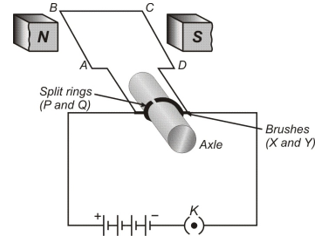
Construction
It consists of the following five parts:
- Armature: the armature abcd consists of a large number of turns of insulated copper wire wound over a soft iron core.
- Field magnet: the magnetic field (b) is supplied by a permanent magnet ns.
- Split-ring or commutator: these are two halves of the same metallic ring. The ends of the armature coil are connected to these halves, which also rotate with the armature.
- Brushes or sliding contacts: these are two flexible metal plates or carbon rods x and y which are so fixed that they constantly touch the revolving rings.
- Battery: the battery consists of a few cells and is connected across the brushes. The brushes pass the current to the rings from where it is carried to the armature.
Working
The working of a dc motor will be clear form the following discussion:
- Let us suppose that the battery sends current to the armature in the direction shown in figure. Applying fleming's left hand rule (motor rule), we find that arm ab experiences a force which is acting outwards and perpendicular to it and arm cd experiences a force which is acting inwards and perpendicular to it. These two forces form a couple which is called torque which makes the armature rotate in the anticlockwise direction.
- After the armature has completed half a revolution (I.E., has turned through 180º), the direction of current in the arms ab and cd is reversed. Now arm cd experiences an outward force and arm ab experiences an inward force. The armature thus continues to rotate about its axis in the same direction, I.E., anticlockwise direction.
The speed of rotation of the motor can be increased by
- Increasing the strength of the current through the armature,
- Increasing the number of turns in the coil of the armature,
- Increasing the area of the coil, and
- Increasing the strength of the magnetic field.
Uses of DC motors
- These are used in electric fans (exhaust, ceiling or table) for cooling and ventilation.
- These are used for pumping water.
- Big dc motors are used for running tram-cars.
- Small dc motors are used in various toys.
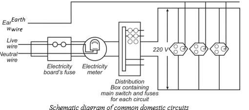
Domestic electric circuits
In our homes, we receive supply of electric power through a main supply which is also called mains. The various other features of domestic electric currents are :
Feature of domestic circuit
Electric cable or overhead wires
The electric power to a house is supplied either through overhead wires or through underground cables. The cable has three separate insulated wires:
- Live wire (or phase or positive)
- Neutral wire (or negative) and
- Earth wire.
The live wire has usually red insulation cover, neutral wire has black insulation cover and the earth wire has green insulation cover. As per the new international convention, live wire has brown coloured insulation cover whereas neutral and earth wires have light blue and green (or yellow) insulation covers. The potential difference between the live and neutral wire is 220 v. The neutral and the earth wires are connected together at the local sub-station so that both of them are at zero potential.
Pole fuse
Before the electric lines enter a house, the agency supplying electricity, places a fuse (called the pole fuse or company fuse) in the live wire. The current rating of this fuse depends upon the load sanctioned by the agency to that house.
Energy meter or kwh meter:
After the company fuse, the cable is connected to the energy meter, which records the electricity consumption of the house in kilowatt, hour (kwh). The earth wire from the meter is locally earthed in the compound of the house.
Distribution board:
Power lines coming from the electricity meter are taken to the distribution board. It is from the distribution board that the wires go to the different parts of the house through fuses in the board.
Why is series arrangement not used for domestic circuits?
In domestic circuits, series arrangement is not used because of the following reasons:
- The total potential difference available (usually 220 volts) is divided between various appliances in the circuit according to their resistances since the current flowing through all the appliances is the same. Thus, each appliance will not get the required potential difference for it to operate properly.
- If one of the appliances is out of order, e.G., if a bulb gets fused or if we switch off one of the appliances all the appliances in the circuit will stop working, as the circuit gets broken.
- All the appliances will work simultaneously whether we want them to work or not, thereby involving a lot of power wastage.
Short-circuiting
In general, short-circuiting occurs when the ends of a circuit are connected by a conductor of very low resistance as compared to that of the circuit. In household connections, short-circuiting occurs when the live (positive) wire and the neutral (negative) wire come in direct contact with each other.
Reasons of short-circuiting
- Dmage to the insulation of the power-lines
- A fault in an electric appliance due to which current does not pass through it.
- Over loading
Consequences of short-circuiting
On account of short-circuiting, resistance of the circuit decreases to a very small value and consequently, the current becomes very large. This large current results in heating of live wires, which produces sparking at the point of short-circuiting. This sparking sometimes causes fire in a building. (apart from short-circuiting, the increase in current in the circuit and consequent heating may also be due to overloading of the circuit).
Electric fuse: A Safety Device
An electric fuse is a device, which is used in series to limit the current in an electric circuit so that it easily melts due to overheating when excessive current passes through it. A fuse is a wire of a material with very low melting point.
A fuse is a wire made of an alloy of lead (75%) and tin (25%), which melts at around 200ºc (low melting point). Electric fuse can avoid incidents like electric shock, fire, damage to an electric appliance due to:
Short-circuiting or Overloading (withdrawing current beyond a specified limit) in a circuit.
When a heavy current flows through the circuit, the fuse wire gets heated and melts. Consequently, the circuit is broken and the current stops flowing in it. A few important points regarding a fuse are as follows :
- In household supply, a fuse is always connected in live wire and not in the neutral wire under any circumstance. Though it will melt even when connected with neutral wire, the electric appliance will continue to be in contact with the live wire. Thus, when the electric appliance is touched, it will give shock.
- A fuse is always connected in the beginning of the circuit before any appliance is connected. This is done to protect the appliance from getting damaged.
- Fuses of various current capacities are available. Remember that thicker the fuse wire, the greater is its current capacity.
- A fuse used must be of current capacity (also called current rating) less than the maximum current which a circuit or an appliance can withstand. A fuse of current capacity of 5 a is put in a line meant to supply power to lights (I.E., bulbs) and fans whereas a fuse of 15 a current capacity is meant for a line which operates an electric heater or a geyser, etc.
Earthing
Many electric appliances of daily use like electric press, toaster, refrigerator, table fan etc. Have a metallic body. If the insulation of any of these appliances melts and makes contact with the metallic casing, the person touching it is likely to receive a severe electric shock. This is due to the reason that the metallic casing will be at the same potential as the applied one. Obviously, the electric current will flow through the body of the person who touches the appliance. To avoid such serious accidents, the metal casing of the electric appliance is earthed. Since the earth does not offer any resistance, the current flows to the earth through the earth wire instead of flowing through the body of the person. Moreover, due to very low resistance (almost nil) offered by the earth wire, the current in the circuit rises to a very high value, thereby melting fuse in that circuit and cutting off its electric supply.
Role of magnetism in medicine and organisms:
In our body, small electric current travels along the nerve cells due to ions. This current produces a very weak magnetic field (about one billionth time weaker than the earth's magnetic field) in our body. Heart and brain are the two main organs in our body where this magnetic field is quite significant. The magnetic field in our body enables us to obtain the images of its different parts by using a technique called mri (magnetic resonance imaging). On analysing the images obtained through mri, we are able to make a medical diagnosis, e.G., location and size of a tumour in brain etc. Thus, magnetism plays an important role in modern medical science.
Apart from this, there are certain organisms, which have the ability to sense earth's magnetic field and travel from one place to another. For example, some type of fishes are able to detect magnetic field by using special receptors whereas in certain organisms, crystals of magnetite enable to move along the earth's magnetic field.
Solved Examples
Q1. Why don't two magnetic lines of force intersect each other?
Sol. No, two magnetic field lines can ever intersect each other. If they do, then it would mean that at the point of intersection there are two directions of magnetic field, which is not possible.
Q2. Name two important properties of a magnet.
Sol. A magnet has
- an attractive property for magnetic substances, and
- a directive property.
Q3. What is the direction of magnetic field lines:
(a) outside magnet.
(b) inside a magnet?Sol.
- From N-pole towards S-pole outside the magnet, and
- from S-pole towards N-pole inside a magnet.
Q4. On what factors does the magnetic field produced at the centre of a current carrying circular loop depend?
Sol. The magnetic field at the centre of a current carrying circular loop is
- directly proportional to current I, and
- inversely proportional to the radius r of the loop.
Q5. Which end of the current carrying solenoid behaves as a N-pole? Which end behaves as a S-pole?
Sol. The end of solenoid, where current appears to be flowing anti-clockwise, behaves as N-pole. The other end where current appears to be flowing clockwise behaves as S-pole.
Q6. On what factors does the magnitude of force experienced by a current carrying conductor placed normally in a magnetic field depend?
Sol. The force depends on
- current flowing in the conductor,
- length of the conductor,
- strength of magnetic field.
Q7. A proton beam is moving along the direction of a magnetic field. What force is acting on proton beam?
Sol. As proton beam is moving parallel to the direction of the magnetic field, no force acts on it. Hence, proton beam goes undeviated.
Q8. List the properties of magnetic lines of force.
Sol. Properties of magnetic lines of force are listed below:
- Outside a magnet, the magnetic field lines are directed from N-pole of magnet towards S-pole. However, inside a magnet, the field lines are directed from S-pole to N-pole. Thus, magnetic field lines are closed curves.
- The magnetic field line at any point, always points in the direction of magnetic field at that point.
- The relative strength of magnetic field lines is given by degree of closeness of the field lines. More crowded field lines means a stronger magnetic field.
- No two magnetic field lines can ever intersect with each other.
Q9. With the help of figure, explain the law of pole formation at the ends of a solenoid carrying current.
Sol. When current is passed through a solenoid coil, from one end current appears to be flowing clockwise but from the other end current appears to be flowing anticlockwise.
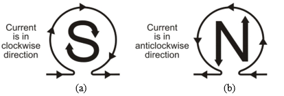
As shown in figure (b), the end of the current carrying solenoid at which the current flows anticlockwise behaves as the North Pole. On the other hand, as shown in figure (a), the end of solenoid at which the current flows clockwise behaves as the South Pole.Q10. What is the principle of an electric motor?
Sol. An electric motor is based on the principle that a current carrying conductor experiences a force when placed in a magnetic field. The direction of the force is given by Fleming's left hand rule.
Q11. Name some sources of direct current and alternating current.
Sol.
- Some sources of direct current are a cell, a battery and a DC generator.
- AC generator and common inverter used in houses for emergency power supply produce alternating current.
Q12. Name two safety measures commonly used in electric circuits and appliances.
Sol. Two safety measures are:
- Use of earth wire and proper earthing,
- Use of fuse
13. What capacity fuse wire is used in power circuit for operating
(i) Refrigerator, geyser or an immersion heater etc.?
(ii) Lighting circuits?Sol.
- 15 A capacity fuse wire.
- 5 A capacity fuse wire.
Q14. Name some common devices that use current carrying conductors and magnetic fields.
Sol. Some common devices that use current carrying conductors and magnetic fields are electric motor, electric generator, loudspeakers, microphones and measuring instruments like galvanometer, ammeter, voltmeter, etc.
Q15. Explain the reason for using
(a) an electromagnet
(b) a coil having large number of turns, and
(c) a soft iron core in an electric motor.Sol.
- We prefer to use an electromagnet in electric motor because its strength can be increased by increasing the current passed through the coil around the electromagnet.
- By using a coil having large number of turns of conducting wire, the magnetic force due to all wires is added up and hence net force becomes very strong.
- Presence of a soft iron core, on which the coil is wound, increases the power of motor.
Q16. On what factors does the force experienced by a current carrying conductor placed in a uniform magnetic field depend?
Sol. The force experienced by a current carrying conductor placed in a uniform magnetic field depends on the flowing factors:
- The force experienced is zero when conductor is placed parallel to the magnetic field. The force is maximum when current carrying conductor is help perpendicular to the direction of magnetic field.
- When placed in perpendicular direction the force on conductor depends on
- The length of conductor,
- The current flowing, and
- Strength of uniform magnetic field.
Q17. How can you show that the magnetic field produced by a given electric current in the wire decreases as the distance from the wire increases?
Sol. For a given current carrying electric wire, place a compass needle near the wire. Now if we move the compass away from the wire, the deflection in the needle continuously decreases. It shows that magnetic field is decreasing on increasing the distance from the wire.
Q18. What is the advantage of the third wire of earth connection in domestic electric appliances?
Sol. The earth wire functions as a safety measure, especially for those appliances that have a metallic body e.g., electric press, toaster, table fan, refrigerator, room cooler etc.
The metallic body of the appliance is connected to the earth wire, which provides a low resistance-conducting path for electric current. It ensures that any leakage of current to the metallic body of an appliance keeps its potential same as of earth. As a result, the user would not get a severe electric shock, even if he touches the body of appliance.
Q19. Explain different ways to induce current in a coil.
Sol. Different ways to induce current in a coil are as given below:
- If a magnetic field is changed around a coil then an induced current is set up in the coil. It can be done by taking a bar magnet and bringing it closer to the coil or taking it away from the coil.
- If a coil is moved in a magnetic field, then again an induced current is set up in the coil.
- If a coil is rotated in a uniform magnetic field, it may also cause an induced current in the coil.
- If we take two coils and insert them over a non-conducting cylindrical roll then on changing current flowing in one coil, an induced current is obtained in the other coil.
Q20. An electric oven of 2 kW power rating is operated in a domestic electric circuit (220 V) that has a current rating of 5 A. What result do you expect? Explain.
Sol. As power rating of electric oven p = 2 kW = 2000 W and supply voltage V = 220 V.
Hence, the electric oven will draw a current I = P/V = 2000 W/220 V = 9 A.
As the current rating of domestic electric circuit is only 5 A and the oven draws a current 9 A, which is more than the current rating, hence the circuit will be damaged due to overheating/overloading.Q21. A coil of insulated copper wire is connected to a galvanometer. What will happen if a bar magnet is
(a) Pushed into the coil,
(b) Withdrawn from inside the coil,
(c) Held stationary inside the coil?Sol.
- When a bar magnet is pushed into the coil of insulated copper wire connected to a galvanometer, an induced current is set up in the coil. As a result, galvanometer gives a deflection (say towards left).
- When the bar magnet is withdrawn from inside the coil, again an induced current is set up in the coil. However, now direction of induced current is opposite to that in earlier case. Hence deflection in galvanometer is in reverse direction (say towards right).
- If the bar magnet is held stationary inside the coil, then there is no induced current in the coil, As a result, galvanometer does not show any deflection.
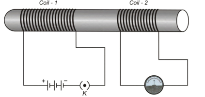
Q22. Two circular coils 1 and 2 are placed close to each other. If the current in the coil 1 is changed, will some current be induced in the coil 2? Give reason.
Sol. Yes, a current is induced in the coil 2.
When the current in the coil A is changed, the magnetic field associated with it also changes. As coil 2 is placed close to 1, hence magnetic field lines around this coil also change. Due to change in magnetic field lines associated with coil 2, a current is also induced in it.
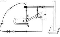
Q23. Demonstrate that due to motion of a magnet near a solenoid coil an induced current is set up in the coil.
Or
Describe an activity to show the phenomenon of electromagnetic induction.
Sol.
Take a solenoid coil of insulated copper wire AB having a number of turns (about 20 or more). Connect the ends of coil to a sensitive galvanometer. Now take a bar magnet NS and rapidly bring the magnet towards the end B or coil as shown in figure. The galvanometer suddenly gives momentary deflection in one direction. Now take the magnet away from the coil, the galvanometer again gives momentary deflection but in the opposite direction. It clearly shows that motion of magnet induces, a current in the coil and it is the phenomenon of electromagnetic induction.
Now fix the magnet in any one position so that it is stationary with respect to the coil. We find that there is no deflection in galvanometer.
Again keep the magnet fixed and gently move the coil AB either towards the magnet or away from the magnet. We get deflection in galvanometer even now. Thus, it is proved that induced current due to electromagnetic induction is produced whenever there is relative motion between the coil and the magnet.
Exercise 1
When a bar magnet is broken into two pieces:
(a) we will have a single pole on each piece
(b) each piece will have two unlike poles
(c) each piece will have two like poles
(d) none of these
The magnetic field intensity produced due to a current carrying coil is maximum at:
(a) any point
(b) the centre of the coil
(c) any point lying on the axis of the coil
(d) points lying between centre of the coil and its circumference
The direction of magnetic lines of force produced by passing a direct current in a conductor is:
(a) perpendicular to the conductor & coming outwards
(b) parallel to conductor
(c) surrounding the conductor and of circular nature
(d) perpendicular to the conductor & coming inwards
Which of the following statement is not correct about two parallel conductors carrying equal currents in the same direction?
(a) Each of the conductors will experience a force.
(b) The two conductors will repel each other.
(c) There are concentric lines of force around each conductor.
(d) Each of the conductors will move if not prevented from doing so.
Which of the following determine the direction of magnetic field due to a current carrying conductor?
(a) Faraday's laws of electromagnetic induction.
(b) Fleming's left-hand rule.
(c) Lenz's law.
(d) Maxwell's cork screw rule.
In the figure QR is a vertical conductor and the current I flows from R to Q. P is a point on the horizontal plane and is to the south of the wire. The direction of the magnetic field at P due to the current will be towards:
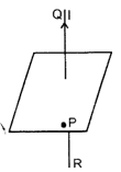
(a) upward
(b) north
(c) east
(d) west
A length of wire carries steady current. It is bent first to form a circular plane coil of one turn. The same length is now bent to give a double loop of smaller radius. The magnetic field produced at the centre by the same current will be:
(a) a quarter of its first value
(b) a half of first value
(c) four times its first value
(d) unaltered
A wire as shown in figure carries a current I ampere. The semicircle has a radius r. The magnetic field at the centre C will be:
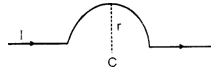
(a) zero
(b) πI × 10⁻⁷/r Newton/ampere-metre
(c) πI/r Newton/ampere-metre
(d) πI/r gauss
The intensity of a magnetic field is defined as the force experienced by a:
(a) standard compass
(b) unit positive charge
(c) unit negative charge
(d) unit north pole
A wire carrying a current of 5A is placed perpendicular to a magnetic induction of 2T. The force on each centimeter of the wire is:
(a) 1 N
(b) 100 N
(c) 0.1 N
(d) 10 N
Force acting on a stationary charge Q in the magnetic field B is -
(a) B Q V
(b) BV/Q
(c) Zero
(d) BQ/V
A proton is moving with velocity 10⁶ m/s parallel to the magnetic field of intensity 5 Tesla. The force on the proton is -
(a) 8 × 10⁻¹⁵ N
(b) 10⁴ N
(c) 1.6 × 10⁻¹⁹ N
(d) Zero
A wire of length l is placed in a magnetic field B, If the current in the wire is I, then maximum magnetic force on the wire is:
(a) BIl
(b) BI/l
(c) Il/B
(d) I/Bl
The permanent magnets are kept with soft iron pieces at ends as keepers:
(a) to magnetise the soft iron pieces
(b) to increase the strength of the magnets
(c) to avoid self demagnetisation
(d) for physical safety of the magnets
In case of a DC generator are the number of coils, each having many turns and arranged in different turns used:
(a) to get high voltage DC
(b) to get high ampere DC
(c) to get smooth DC
(d) to get pulsating current
Lenz's law is a consequence of the law of conservation of:
(a) energy
(b) momentum
(c) angular momentum
(d) charge and mass
In a DC generator, the induced e.m.f. in the armature is:
(a) DC
(b) AC
(c) fluctuating DC
(d) both AC and DC
The induced emf produced when a magnet is inserted into a coil does not depend upon:
(a) the number of turns in the coil
(b) the resistance of the coil
(c) the magnetic moment of the magnet
(d) the speed of approach of the magnet
Lenz's law:
(a) is the same as, the right hand palm rule
(b) determines the magnitude of an induced emf
(c) bears no relation to the law of conservation of energy
(d) is useful in deciding about the direction of an induced emf
When the current through a solenoid increases at a constant rate, the induced current:
(a) is a constant and in the direction of inducing current
(b) is a constant and is opposite to the direction of inducing current
(c) increases with time and is in the direction of inducing current
(d) increases with time and is opposite to the direction of inducing current
The current in the armature of a dc motor is maximum when:
(a) the motor achieves maximum speed
(b) the motor achieves intermediates speed
(c) the motor is switched on
(d) the motor is switched off
The affect of using split rings in a simple DC motor is that:
(a) the direction of rotation of the coil is reversed
(b) the current in the coil always flows in the same direction
(c) the direction of the current flowing in the coil is reversed
(d) none of these
The magnetic field inside a long straight solenoid-carrying current
(a) Is zero
(b) Decreases as we move towards its end
(c) Increases as we move towards its end
(d) Is the same at all points
When the normal to a coil points in the direction of B, the flux is
(a) Positive
(b) Negative
(c) Zero
(d) Nothing can be said
In a DC generator, the induced emf in the armature is
(a) DC
(b) AC
(c) Fluctuating DC
(d) Both AC and DC
A rectangular coil of copper wires is rotated in a magnetic field. The direction of the induced current changes once in each
(a) Two revolutions
(b) One revolution
(c) Half revolution
(d) One-fourth revolution
Which of the following correctly describes the magnetic field near a long straight wire?
(a) The field consists of straight lines perpendicular to the wire.
(b) The field consists of straight lines parallel to the wire.
(c) The field consists of radial lines originating from the wire.
(d) The field consists of concentric circles centred on the wire.
Ampere rule is used to find the
(a) Direction of current
(b) Direction of magnetic field
(c) Direction of motion of the conductor
(d) magnitude of current
A compass needle just above a wire in which electrons are moving to the east, will point
(a) East
(b) West
(c) North
(d) South
By increasing the number of turns in the coil, the strength of the magnetic field
(a) Increases
(b) Decreases
(c) First decreases then increases
(d) Remains uncharged
Fleming's right hand rule gives
(a) The magnitude of the induced emf
(b) The magnitude of the magnetic field
(c) The direction of the induced emf
(d) Both magnitude and direction of the induced emf
For making an electromagnet the best material use for the case is
(a) Stainless steel
(b) Soft iron
(c) Silver
(d) Nickel
A wire carrying a current of 5 A is placed perpendicular to a magnetic induction of 2 T. The force on each centimeter of the wire is
(a) 0.1 N
(b) 10 N
(c) 100 N
(d) 1 N
There will be no force between two currents if they are
(a) Parallel to each other
(b) Antiparallel to each other
(c) Perpendicular to each other
(d) Nothing can be said
A copper ring is moved towards the north pole of a bar magnet. Then
(a) The ring will not be affected
(b) The ring will tend to get warm
(c) An alternating current will flow in the ring
(d) The ring will be positively charged
The split rings in motion are called
(a) Armature
(b) Commutator
(c) Rotor
(d) Core
The frequency of AC mains is
(a) 100 Hertz
(b) 50 Hertz
(c) 1/100 Hertz
(d) 1/50 Hertz
A switch is always connected to the
(a) Earth wire
(b) Neutral wire
(c) Live wire
(d) None of these
A fuse wire is always connected to the
(a) Earth wire
(b) Neutral wire
(c) Live wire
(d) None of these
The frequency of AC used in India is
(a) 50 Hz
(b) 100 Hz
(c) 200 Hz
(d) none of these
Which of the following figures represents the magnetic lines of force due to an isolated north pole?
(a) Lines radiating outward from N
(b) Lines going inward to N
(c) Lines forming loops around N
(d) Lines parallel to N
Magnetic lines of force
(a) Form closed circuits
(b) Cannot intersect
(c) Are crowded together near the poles
(d) All the above are correct
A coil carrying current behaves as a/an
(a) Magnet
(b) Motor
(c) Dynamo
(d) Electric dipole
The wire having red plastic covering is a
(a) Live wire
(b) Neutral wire
(c) Earth wire
(d) None of these
The wire having black plastic covering is a
(a) Live wire
(b) Neutral wire
(c) Earth wire
(d) None of these
The wire having green plastic covering is a
(a) Live wire
(b) Neutral wire
(c) Earth wire
(d) None of these
Which of the following is not associated with Fleming's left hand rule?
(a) Resistance
(b) Magnetic field
(c) Force
(d) Current
If a bar magnet is cut lengthwise into 3 parts, the total number of poles will be
(a) 2
(b) 3
(c) 4
(d) 6
A compass needle placed just above a wire in which electrons are moving towards west, will point
(a) East
(b) North
(c) West
(d) South
Magnetic effect of electric current was discovered by
(a) Maxwell
(b) Oersted
(c) Ampere
(d) none of these
Electric bulb converts electrical energy into
(a) Sound energy
(b) Mechanical energy
(c) Nuclear energy
(d) None of these
Choose the wrong statement
(a) Magnetic poles always exist in pairs
(b) Magnetic poles are always of equal strength
(c) Like poles repel each other
(d) Unlike poles repel each other
Answer to Exercise 1
| 1. | (b) | 2. | (b) | 3. | (c) | 4. | (b) | 5. | (d) |
| 6. | (c) | 7. | (c) | 8. | (b) | 9. | (d) | 10. | (c) |
| 11. | (c) | 12. | (d) | 13. | (a) | 14. | (c) | 15. | (c) |
| 16. | (a) | 17. | (b) | 18. | (b) | 19. | (d) | 20. | (b) |
| 21. | (d) | 22. | (c) | 23. | (d) | 24. | (a) | 25. | (b) |
| 26. | (c) | 27. | (d) | 28. | (b) | 29. | (d) | 30. | (b) |
| 31. | (c) | 32. | (c) | 33. | (a) | 34. | (c) | 35. | (b) |
| 36. | (c) | 37. | (b) | 38. | (c) | 39. | (c) | 40. | (a) |
| 41. | (a) | 42. | (d) | 43. | (a) | 44. | (a) | 45. | (b) |
| 46. | (c) | 47. | (a) | 48. | (d) | 49. | (b) | 50. | (b) |
| 51. | (d) | 52. | (d) |
Exercise 2
A very small magnet is placed in the magnetic meridian with its south pole pointing north. The null point is obtained 20 cm away from the centre of the magnet. If the earth's magnetic field (horizontal component) at this point be 0.3 gauss, the magnetic moment of the magnet
(a) 8.0 × 10² e.m.u.
(b) 1.2 × 10³ e.m.u.
(c) 2.4 × 10³ e.m.u.
(d) 3.6 × 10³ e.m.u.
Earth's magnetic field always has a horizontal component except at or Horizontal component of earth's magnetic field remains zero at
(a) Equator
(b) Magnetic poles
(c) A latitude of 60°
(d) An altitude of 60°
The lines joining the places of the same horizontal intensity are known as
(a) Isogonic lines
(b) Aclinic lines
(c) Isoclinic lines
(d) Agonic lines
(e) Isodynamic lines
The magnetic compass is not useful for navigation near the magnetic poles because
(a) The magnetic field near the poles is zero
(b) The magnetic field near the poles is almost vertical
(c) At low temperature, the compass needle looses its magnetic properties
(d) Neither of the above
At the magnetic north pole of the earth, the value of horizontal component of earth's magnetic field and angle of dip are, respectively
(a) Zero, maximum
(b) Maximum, minimum
(c) Maximum, maximum
(d) Minimum, minimum
Magnetic meridian is a
(a) Point
(b) Horizontal plane
(c) Vertical plane
(d) Line along N-S
The value of angle of dip is zero at the magnetic equator because on it
(a) V and H are equal
(b) The value of V and H is zero
(c) The value of V is zero
(d) The value of H is zero
At which place, earth's magnetism become horizontal
(a) Magnetic pole
(b) Geographical pole
(c) Magnetic meridian
(d) Magnetic equator
If magnetic lines of force are drawn by keeping magnet vertical, then number of neutral points will be
(a) One
(b) Two
(c) Four
(d) Five
Time period of a freely suspended magnet does not depend upon
(a) Length of the magnet
(b) Pole strength of the magnet
(c) Horizontal component of earth's magnetic field
(d) Length of the suspension thread
Vibration magnetometer is used for comparing
(a) Magnetic fields
(b) Earth's field
(c) Magnetic moments
(d) All of the above
Time period for a magnet is T. If it is divided in four equal parts along its axis and perpendicular to its axis as shown then time period for each part will be
(a) 4T
(b) T/4
(c) T/2
(d) T
The period of oscillation of a magnet in vibration magnetometer is 2 sec. The period of oscillation of a magnet whose magnetic moment is four times that of the first magnet is
(a) 1 sec
(b) 4 sec
(c) 8 sec
(d) 0.5 sec
If a brass bar is placed on a vibrating magnet, then its time period
(a) Decreases
(b) Increases
(c) Remains unchanged
(d) First increases then decreases
To compare magnetic moments of two magnets by vibration magnetometer, 'sum and difference method' is better because
(a) Determination of moment of inertia is not needed which minimises the errors
(b) Less observations are required
(c) Comparatively less calculations
(d) All the above
The time period of oscillation of a magnet in a vibration magnetometer is 1.5 seconds. The time period of oscillation of another magnet similar in size, shape and mass but having one-fourth magnetic moment than that of first magnet, oscillating at same place will be
(a) 0.75 sec
(b) 1.5 sec
(c) 3 sec
(d) 6 sec
Which of the following statement is true about magnetic moments of atoms of different elements
(a) All have a magnetic moment
(b) None has a magnetic moment
(c) All acquire a magnetic moment under external magnetic field and in same direction as the field
(d) None of the above statements are accurateThe sensitivity of a tangent galvanometer is increased if
(a) Number of turn decreases
(b) Number of turn increases
(c) Field increases
(d) None of the above
The time period of a thin bar magnet in earth's magnetic field is T. If the magnet is cut into two equal parts perpendicular to its length, the time period of each part in the same field will be
(a) T/2
(b) T
(c) √2 T
(d) 2T
Magnets cannot be made from which of the following substances
(a) Iron
(b) Nickel
(c) Copper
(d) All of the above
33.
Which of the following is most suitable for the core of electromagnets(a) Soft iron
(b) Steel
(c) Copper-nickel alloy
(d) AirDemagnetisation of magnets can be done by
(a) Rough handling
(b) Heating
(c) Magnetising in the opposite direction
(d) All the above
If a diamagnetic substance is brought near north or south pole of a bar magnet, it is
(a) Attracted by the poles
(b) Repelled by the poles
(c) Repelled by the north pole and attracted by the south pole
(d) Attracted by the north pole and repelled by the south pole
The material of permanent magnet has
(a) High retentivity, low coercivity
(b) Low retentivity, high coercivity
(c) Low retentivity, low coercivity
(d) High retentivity, high coercivity
Which of the following is diamagnetism
(a) Aluminium
(b) Quartz
(c) Nickel
(d) Bismuth
If a ferromagnetic material is inserted in a current carrying solenoid, the magnetic field of solenoid
(a) Largely increases
(b) Slightly increases
(c) Largely decreases
(d) Slightly decrease
A frog can be deviated in a magnetic field produced by a current in a vertical solenoid placed below the frog. This is possible because the body of the frog behaves as
(a) Paramagnetic
(b) Diamagnetic
(c) Ferromagnetic
(d) Antiferromagnetic
Which one of the following is a non-magnetic substance
(a) Iron
(b) Nickel
(c) Cobalt
(d) Brass
Answers to Exercise– 2
1. (b)
2. (b)
3. (e)
4. (b)
5. (a)
6. (c)
7. (c)
8. (d)
9. (a)
10. (d)
11. (d)
12. (c)
13. (a)
14. (b)
15. (d)
16. (c)
17. (d)
18. (b)
19. (a)
20. (c)
21. (a)
22. (d)
23. (b)
24. (d)
25. (d)
26. (a)
27. (b)
28. (d)
Key Topics Covered
-
Magnetic Field and Field Lines – Invisible region around a magnet where force is experienced. Field lines are closed curves.
-
Magnetic Field due to Current – The right-hand thumb rule explains the direction of the field around a straight conductor.
-
Magnetic Field in Solenoid – Similar to a bar magnet, a strong and uniform field inside.
-
Force on a Current-Carrying Conductor – Direction determined by Fleming’s Left-Hand Rule.
-
Electric Motor – A Device that converts electrical energy into mechanical energy.
-
Electromagnetic Induction – Current induced in a coil due to a change in the magnetic field. Explained by Faraday’s Law.
-
Electric Generator – A Device that converts mechanical energy into electrical energy.
-
Fleming’s Right-Hand Rule – Used to find the direction of the induced current.
Important Questions – Magnetism
-
Draw magnetic field lines for a bar magnet.
-
State the Right-Hand Thumb Rule with an example.
-
Explain the principle and working of an electric motor.
-
What is electromagnetic induction? Give one example.
-
Differentiate between an AC generator and a DC generator.
Why These Notes are Useful
-
Contains diagrams of motor, generator, and field lines.
-
Covers laws and rules with applications.
-
Includes high-weightage questions asked in board exams.
Preparation Tips
-
Practice Fleming’s rules with examples.
-
Revise diagrams of the motor and generator carefully.
-
Solve numerical problems on force and current.
Conclusion
The chapter Magnetism is scoring with a focus on diagrams and rules. These physics notes and solved questions provide complete preparation material for board exams.