What is Light? Exploring the Dual Nature of Electromagnetic Radiation
Light represents one of the most fascinating phenomena in physics a form of electromagnetic energy that enables vision and underpins countless natural and technological processes. Light is a form of electromagnetic energy that causes the sensation of vision. The study of light, known as optics, encompasses multiple branches including geometrical optics (reflection and refraction), wave optics (interference, diffraction, and polarization), and quantum optics (photoelectric effect and atomic interactions).
The Evolution of Light Theory: From Particles to Waves to Photons
The understanding of light has evolved dramatically through scientific history. Newton's particle theory proposed that light travels as a stream of tiny corpuscles, but this theory failed to explain interference and diffraction phenomena, leading to acceptance of the wave theory. Today's modern quantum theory reconciles these perspectives, recognizing light's dual nature behaving as both waves and particles depending on the experimental context.
When light falls on metal surfaces like caesium or potassium, electrons are ejected a phenomenon called the photoelectric effect, explained by Einstein using Planck's concept that light consists of energy packets called photons. Each photon carries energy E = hν, where h represents Planck's constant (6.6 × 10⁻³⁴ J·s) and ν denotes the light's frequency.
The wavelength of visible light ranges from approximately 4 × 10⁻⁷ m (violet) to 8 × 10⁻⁷ m (red), traveling at a remarkable speed of 3 × 10⁸ m/s in vacuum. This dual wave-particle nature allows light to exhibit both interference patterns (wave behavior) and photoelectric effects (particle behavior).
Reflection of Light: Laws, Types, and Mirror Optics
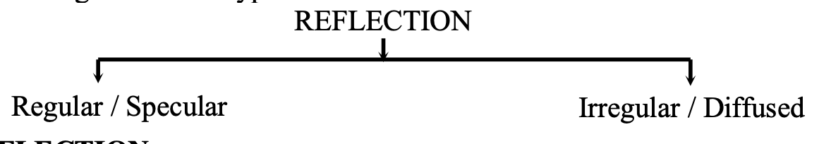
Reflection: Regular vs. Irregular
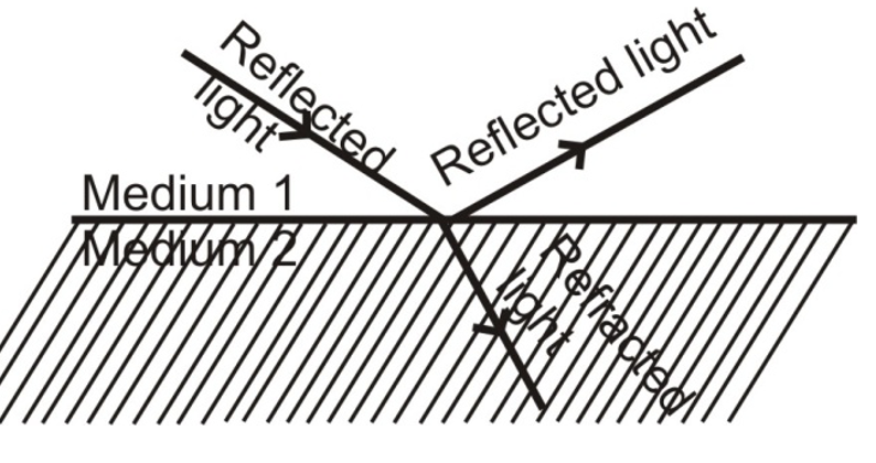
When light traveling in one medium falls on a surface, part of the incident light returns to the first medium—this phenomenon is known as reflection of light. Reflection manifests in two distinct forms:
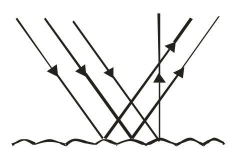
Regular (Specular) Reflection occurs when parallel incident rays reflect from a smooth, polished surface like a mirror, producing parallel reflected rays that travel in a specific direction. The laws of reflection are valid only in regular reflection, which makes objects visible.
Irregular (Diffused) Reflection happens when parallel incident rays strike a rough surface and reflect in multiple directions. In irregular reflection, only the surface is visible, not a clear image, and the laws of reflection are not applicable in the conventional sense.
The Fundamental Laws of Reflection
According to the first law of reflection, the incident ray, reflected ray, and normal at the point of incidence all lie in the same plane perpendicular to the reflecting surface.
The second law states that the angle of incidence always equals the angle of reflection (∠i = ∠r) for small angles. This principle applies universally to all mirrors, whether plane or spherical.
A particularly important consequence: A ray of light incident normally (perpendicularly) on a reflecting surface is reflected back along the same path because both the angle of incidence and angle of reflection equal zero.
Spherical Mirrors: Concave and Convex
Spherical mirrors curved reflecting surfaces forming part of a hollow sphere come in two types: concave mirrors (converging) where the reflecting surface curves inward, and convex mirrors (diverging) where it curves outward.
Terms in Spherical Mirror Optics
The centre of curvature (C) represents the centre of the imaginary sphere from which the mirror is a part, while the radius of curvature (R) is the radius of that imaginary sphere. The pole (P) is the centre of the mirror's reflecting surface, and the principal axis is the straight line passing through both the centre of curvature and the pole.
The focal length is the distance between the pole and the focus, which equals half the radius of curvature: f = R/2.
Image Formation by Concave Mirrors
Concave mirrors produce different image characteristics depending on object position:
- Object at infinity: Real, inverted, highly diminished image at focus F
- Object beyond 2F: Real, inverted, diminished image between F and 2F
- Object at 2F: Real, inverted, same-size image at 2F
- Object between F and 2F: Real, inverted, enlarged image beyond 2F
- Object at F: Real, inverted, highly magnified image at infinity
- Object between P and F: Virtual, erect, enlarged image behind mirror
Concave mirrors serve as shaving mirrors, reflectors in headlights and torches, medical examination instruments, and solar energy collectors.
Convex Mirrors: Always Virtual and Diminished
Convex mirrors invariably produce virtual, erect, and diminished images regardless of object position, making them ideal as rear-view mirrors in vehicles because they provide a wide field of view.
Refraction of Light: Bending Through Different Media
The Phenomenon and Cause of Refraction
When light passes from one transparent medium to another, the direction of its path changes at the interface this phenomenon is called refraction of light. The path in the first medium is the incident ray, while in the second medium it becomes the refracted ray.
Light refracts because its speed differs in different media—the speed is maximum in vacuum and decreases in denser media. This variation in optical density causes the characteristic bending:
- Light traveling from an optically rarer to denser medium bends toward the normal
- Light traveling from denser to rarer medium bends away from the normal
- Light traveling along the normal passes undeviated (∠i = ∠r = 0°)
Snell's Law and Refractive Index
According to Snell's law (the second law of refraction), the ratio of sine of the angle of incidence to sine of the angle of refraction is constant for light of a given wavelength and pair of media.
This constant is the refractive index, defined multiple ways:
Refractive index = Speed of light in vacuum / Speed of light in medium
It can also be expressed as the ratio of wavelength in vacuum to wavelength in the medium.
The relative refractive index of medium 2 with respect to medium 1 equals the ratio of light speed in medium 1 to light speed in medium 2.
Common refractive indices include: water (1.33), crown glass (1.52), dense flint glass (1.65), and diamond (2.42).
Practical Effects of Refraction
Refraction produces several observable phenomena:
- Apparent depth: Objects submerged in water appear raised—swimming pools look shallower than their actual depth due to refraction.
- Atmospheric refraction: The sun appears visible a few minutes before actual sunrise and after sunset because light bends through atmospheric layers of varying density, making each day approximately four minutes longer.
- Twinkling of stars: Stars twinkle because atmospheric density variations cause the refractive index to fluctuate, changing the path and intensity of starlight reaching observers.
Lenses: Converging and Diverging Light
Types and Characteristics of Lenses
A lens is a transparent refracting material bounded by two spherical surfaces (or one spherical and one plane surface), serving as the most important optical component in microscopes, telescopes, cameras, and projectors.
Convex (Converging) Lenses are thick at the centre and thin at the edges, including double convex, plano-convex, and concavo-convex forms. They converge parallel light rays to a real focus.
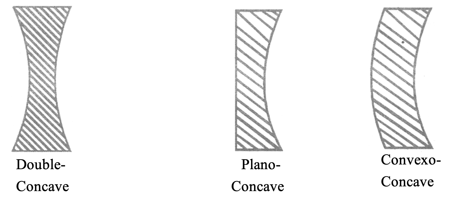
Concave (Diverging) Lenses are thin at the centre and thick at the edges, including double concave, plano-concave, and convexo-concave forms. They diverge parallel light rays from a virtual focus.
Image Formation Rules for Lenses
Convex Lens Ray Tracing
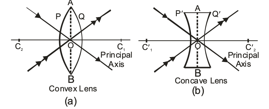
For convex lenses, a ray parallel to the principal axis passes through the focus after refraction, a ray through the optical centre passes straight without deviation, and a ray through the focus emerges parallel to the principal axis.
Image characteristics vary by object position:
- Object at infinity: Real, inverted, highly diminished at F
- Object beyond 2F: Real, inverted, diminished between F and 2F
- Object at 2F: Real, inverted, same size at 2F
- Object between F and 2F: Real, inverted, magnified beyond 2F
- Object at F: Real, inverted, highly magnified at infinity
- Object between O and F: Virtual, erect, magnified on same side
Concave Lens: Always Virtual
Concave lenses invariably produce virtual, erect, and diminished images positioned between the focus F₁ and optical centre O, regardless of object placement.
Essential Formulas in Light and Optics
| Formula Name | Mathematical Expression | Explanation |
| Mirror Formula | 1/f = 1/v + 1/u | Relates focal length (f), image distance (v), and object distance (u) for spherical mirrors |
| Radius-Focal Length Relation | R = 2f | Radius of curvature equals twice the focal length |
| Linear Magnification (Mirror) | m = -v/u = h'/h | Ratio of image distance to object distance, or image height to object height |
| Snell's Law | sin i / sin r = constant = n₂/n₁ | Ratio of sines of angles equals refractive index ratio |
| Refractive Index (Speed) | n = c/v | Speed of light in vacuum divided by speed in medium |
| Refractive Index (Wavelength) | n = λ₀/λ | Wavelength in vacuum divided by wavelength in medium |
| Apparent Depth | n = Real depth / Apparent depth | Refractive index relates actual and perceived depth |
| Lens Formula | 1/f = 1/v - 1/u | Relates focal length, image distance, and object distance for lenses |
| Magnification (Lens) | m = v/u = h'/h | Ratio of image to object distance, or heights |
| Photon Energy | E = hν | Energy of photon equals Planck's constant times frequency |
| Power of Mirror | P = -1/f (in dioptres) | Optical power inversely proportional to focal length |
Light as Foundation of Optical Science
Understanding light from its dual wave-particle nature through reflection and refraction to practical applications in mirrors and lenses forms the foundation of modern optics and photonics. These principles enable technologies ranging from eyeglasses and cameras to fiber optic communications and laser systems. The mathematical relationships governing light behavior provide precise predictive power, while experimental observations continue refining our understanding of this fundamental phenomenon.
For students and educators, mastering these concepts requires both theoretical comprehension and practical application through ray diagrams, calculations, and hands-on experiments with mirrors and lenses. The journey from Newton's corpuscular theory to Einstein's photons illustrates how scientific understanding evolves through rigorous inquiry and evidence-based reasoning.
LIGHT
Light is a form of electromagnetic energy that causes the sensation of vision.
NATURE OF LIGHT
The study of light is called optics and is classified in the following ways:
OPTICS:
It is the branch of physics which deals with the study of light. It is mainly divided into three parts:
(i) Geometrical optics or ray optics: It deals with the reflection or refraction of light.
(ii) Wave or physical optics: It is concerned with nature of light and deals with interference, diffraction and polarization.
(iii) Quantum optics: It deals with the interaction of light with the atomic entities of matter such as Photo Electric effect, atomic excitation etc.
PARTICLE THEORY OF LIGHT:
According to Newton, light travels in space with a great speed as a stream of very small particles called corpuscles. This theory failed to explain the interference of light as well as the diffraction of light. So a wave theory of light was accepted.
WAVE THEORY OF LIGHT:
According to the wave theory, light consists of electromagnetic waves. The light waves travel with a very high speed of 3 × 10⁸ m/s in vacuum.
The wavelength of visible light waves lies between 4 × 10⁻⁷ m to 8 × 10⁻⁷ m.
The phenomenon of diffraction (bending of light around the corners of tiny objects) interference and polarization of light can only be explained if the light is considered to be of wave nature.
MODERN QUANTUM THEORY OF LIGHT:
When light falls on the surface of metals like Caesium, Potassium etc., Electrons are thrown out. These electrons are called ‘photo-electrons’ and the phenomenon is called ‘photo-electric effect.’
This was explained by Einstein. According to Planck, light consisted of packets or quanta of energy called photons. Plank also studied this problem much earlier and constructed a mathematical model, according to which light consists of packets or quantas of energy. Einestein explained this later in 1905. He named a quantum of energy as ‘Photon’. The rest mass of photon is zero. Each quanta carries energy E= hv.
v → Planck’s constant = 6.6 × 10⁻³⁴ J-s.
v → frequency of light
Einstein’s photo-electric equation is h (v - v0)= 1/2 mv2max .
hvo = amount of energy spent in ejecting and electron out of metal surface.
Vmax= maximum velocity of the ejected electron.
Some phenomenon’s like interference of light, diffraction of light are explained with the help of wave theory but wave theory failed to explain the photo electric effect. It was explained with the help of quantum theory. So, light has dual nature.
(i) Wave nature
(ii) Particle nature
SOME IMPORTANT TERMS RELATED WITH LIGHT
ELECTROMAGNETIC WAVES
The waves which do not require a material medium for their propagation are known as electromagnetic waves. e.g. All light waves are electromagnetic waves.
SOURCE OF LIGHT:
A body which emits light in all directions is said to be the source of light. The source can be a point source one or an extended one. The sources of light are of two types:
(i) Luminous source : Any object which by itself emits light is called as a luminous source. e.g. Sun and Stars (natural Luminous sources), Electric lamps, Candles and Lanterns (artificial luminous sources).
(ii) Non-luminous source : Those objects which do not emit light but become visible when light from luminous objects falls on them and they reflect it back. They are called non-luminous. e.g. Moon, Planets (natural non-luminous sources), Wood, Table (artificial non-luminous sources).
TYPES OF MEDIUM:
When light falls on a medium, it can be treated in three ways.
A medium is a substance through which light propagates or tries to do so. Based on this interaction mediums are classified into three categories.
(i) Transparent: The medium which allows most of the light to pass through it is called a transparent medium. e.g. Air, Water, Glass etc.
(ii) Translucent: The medium which allows only a part of the light to pass through it is called a translucent medium. e.g. Paper, Ground glass etc.
(iii) Opaque: The medium which does not allow any light to pass through it is called opaque medium. e.g. Wood, Bricks, Metals etc.
RAY:
A ray of light is the straight line path along which the light travels. It is represented by an arrow head on a straight line (→/ray) . The direction of arrow gives the direction of propagation of light.
BEAM OF LIGHT
A group of parallel rays is called a beam of light. It is also called a pencil of light.
A pencil of light or a beam of light may be of three types.
(i) Convergent pencil
(ii) Divergent Pencil
(iii) Parallel Pencil
Convergent Pencil
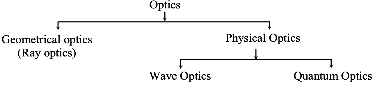
Convergent pencil is also known as convergent beam of light. In this case, as the beam of light progresses the rays converge to a point.
Or
A convergent Pencil is that in which rays of light propogate to meet at a particular point say O as shown in the figure.
The diameter of the pencil goes on decreasing as the rays proceed forward.
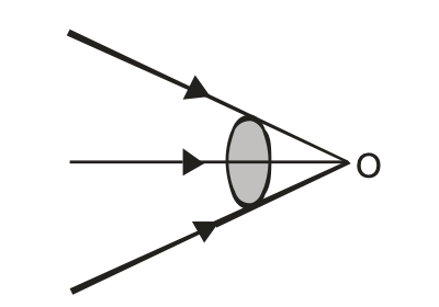
Divergent Pencil
Divergent pencil is also known as divergent beam of light. Here, as the beam of light progresses, the rays diverge from each other.
Or
A divergent pencil is that in which rays of light come out of a point source such that the diameter of the pencil goes on increasing as the rays proceed forward, as shown in the figure.
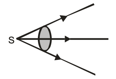
Parallel Pencil
Parallel pencil is that in which all the rays move parallel to one another. The diameter of the pencil remains constant throughout as shown in the figure 3.
BEHAVIOUR OF LIGHT AT THE INTERFACE OF TWO MEDIA:
When light traveling in one medium falls on the surface of a second medium the following three effects may occur :
(i) A part of the incident light is turned back into the first medium. This process is called the reflection of light.
(ii) A part of the incident light is transmitted into the second medium along a changed direction. This is called refraction of light.
(iii) The remaining third part of light energy is absorbed by the second medium. This is called absorption of light.
REFLECTION OF LIGHT
When a beam of light falls on any surface, a part of that is sent back into the same medium from which it is coming. This phenomenon is known at the reflection of light.
Reflection of light is of two types:
REGULAR REFLECTION
When the reflecting surface is smooth and well polished, e.g. mirror, the parallel rays falling on it are reflected parallel to one another i.e. the reflected light goes in one particular direction as shown in the figure. Then it is known as a regular reflection.
The laws of reflection are valid only in regular reflection. It is the regular reflection that makes the object visible.
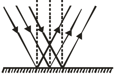
IRREGULAR REFLECTION:
When the reflecting surface is rough, the parallel rays falling on it are reflected in different directions as shown in the figure. Such a reflection is known as irregular reflection or diffused reflection or scattering of light.
Laws of reflection are not validin irregular reflection. In this case only the surface is visible and not the image.
SOME IMPORTANT TERMS USED IN THE REFLECTION OF LIGHT
Let us consider the reflection of light by a plane mirror as shown in the diagram.
INCIDENT RAY:
Any ray of light that strikes the reflecting surface is called the incident ray. In the below figure ‘AO’ is the incident ray.
POINT OF INCIDENCE:
The point of incidence is that point at which light is incident on the reflecting surface. i.e., the point at which the incident ray falls on the reflecting surface.
In below figure ‘O’ is the point of incidence.
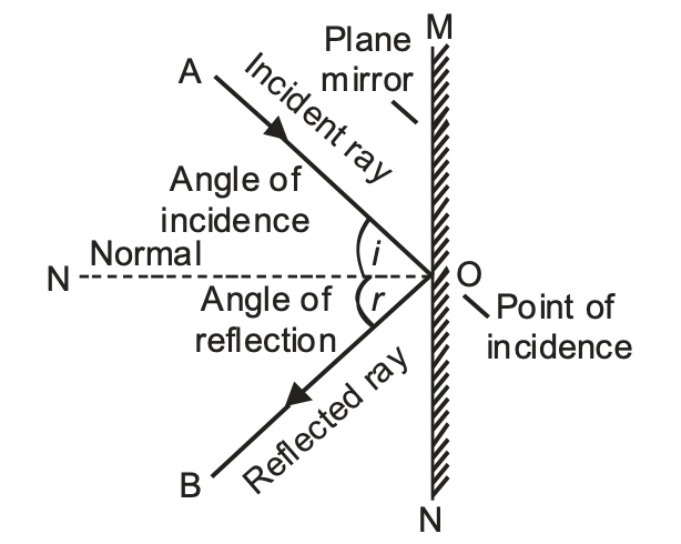
NORMAL:
The perpendicular drawn to the reflecting surface at the point of incidence is called normal. In the above figure, ‘ON’ is the normal.
REFLECTED RAY:
The ray of light which is turned back after reflection into the same medium in which the incident light is travelling is called the reflected ray.
In above figure OB is the reflected ray.
ANGLE OF INCIDENCE:
The angle of incidence is the angle made by the incident ray with the normal at the point of incidence.
Or
The angle between the incident ray and the normal to the surface is called angle of incidence.
In the above figure, ∠AON is the angle of incidence.
ANGLE OF REFLECTION:
The angle of reflection is the angle made by the reflected ray with the normal at the point of incidence.
Or
The angle between the reflected ray and normal to the surface is called the angle of reflection. In ∠BON is the angle of reflection.
LAWS OF REFLECTION
There are two laws of reflection
FIRST LAW OF REFLECTION:
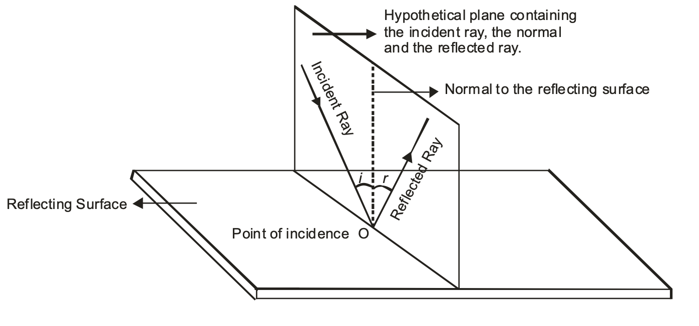
According to the first law of reflection, the incident ray, the reflected ray and the normal at the point of incidence all lie in the same plane which is perpendicular to the plane of the reflecting surface.
SECOND LAW OF REFLECTION:
According to the second law of reflection, the angle of incidence is always equal to the angle of reflection for small angles.
i.e. ∠i =∠r
Where ∠i = angle of incidence.
∠r = angle of reflection.
The laws of reflection of light apply to all kinds of mirrors, plane mirrors as well as spherical mirrors.
MIRROR:
It is a highly polished surface, which is quite smooth the capable of reflecting a good fraction of light from its surface.
(a) Object:
Anything which gives out light rays (either its own or reflected) is called an object.
(i) Real object: All physical objects and light sources are real which either scatter light rays or produces light rays.
(ii) Virtual object: When converging incident rays are incident on eye or an optical device, there is no single point from which light rays actually come. In this case we say the object is virtual.
IMAGES
The reproduction of object formed by mirror or lens is called an image.
An image is formed when the light rays coming from an object actually meet (or appear to meet) at a point after reflection or refraction.
Images are of two types.
REAL IMAGE:
The real image is formed due to real intersection of reflected or refracted rays. Real images can be obtained on screen.
Or
The image formed when two or more reflected or refracted rays intersect each other at a point in front of the reflecting surface (mirror) is known as a real image. It can be obtained on a screen.
e.g. The images formed on a cinema screen are real images.
VIRTUAL IMAGE:
The virtual image is formed due to apparent intersection of reflected or refracted light rays. Virtual images can’t be obtained on screen.
Or
The image formed when two or more reflected or refracted rays appear to intersect at a point behind the normal. It can’t be obtained on a screen.
e.g. The image of our face in a plane mirror is a virtual image.
TYPES OF MIRROR:
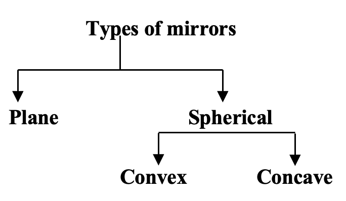
PLANE MIRROR
Any smooth, highly polished reflecting surface is called a mirror. A plane mirror is a highly polished plane surface.
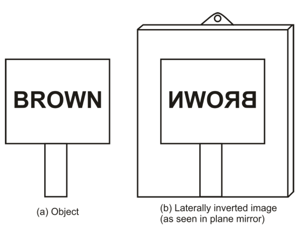
CHARACTERISTICS OF IMAGE FORMED BY PLANE MIRRORS:
Following are the important characteristics of image formed by plane mirrors.
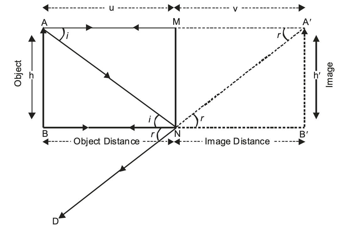
- The image formed in a plane mirror is always virtual. Such an image cannot be taken on a screen.
- The image formed in a plane mirror is always erect. It is the same side up as the object.
- The image in a plane mirror is of the same size as the object.
- The image formed by a plane mirror is at the same distance behind the mirror as the object is in front of the mirror i.e. Image distance is always equal to the object distance in a plane mirror.
- The image formed in a plane mirror is laterally inverted i.e. the left side of the object becomes the right side of the image and vice-versa.
SPHERICAL MIRRORS:
A mirror whose reflecting surface is a part of a hollow sphere is known as spherical mirror. For example, a dentist uses a curved mirror to examine the teeth closely, large curved mirrors are used in telescope at observatories.
These are of the type convex and concave.
SOME IMPORTANT TERMS RELATED TO SPHERICAL MIRRORS
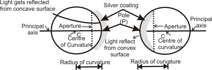
CENTRE OF CURVATURE (C):
The centre of curvature of a spherical mirror is the centre of the imaginary hollow sphere of glass, of which the spherical mirror is a part. The centre of curvature is usually denoted by the letter C. The centre of curvature of a concave mirror is in front of it and the centre of curvature of convex mirror is behind the mirrors as shown in the figure.
RADIUS OF CURVATURE (R):
The radius of curvature of a spherical mirror is the radius of the imaginary hollow sphere of glass, of which the spherical mirror is a part. The radius of curvature is usually denoted by the letter ‘R’.
In figure above the distance PC is the radius of curvature of a concave mirror and in figure (b) the distance PC is the radius of curvature of a convex mirror.
POLE (P) :
The centre of the reflecting surface of a spherical mirror is called its pole. It is usually denoted by the letter ‘P’ in each concave and convex mirror. The pole of a spherical mirror lies on the surface of the mirror.
PRINCIPAL AXIS:
The principal axis of a spherical mirror is the straight line passing through the centre of curvature C and pole P of a spherical mirror, produced on both sides.
APERTURE:
The portion of a mirror from which the reflection of light actually takes place is called the aperture of the mirror. It is also called linear aperture of the mirror. The aperture of a spherical mirror is denoted by the diameter of its reflecting surface.
FOCAL PLANE:
A plane passing through the principal focus and at right angles to the principal axis of a spherical mirror is called its focal plane.
FOCAL LENGTH:
The distance between the pole and the focus is called the focal length. The focal length is half the radius of curvature.
PRINCIPAL FOCUS:
|
Focus of concave mirror |
Focus of convex mirror |
|
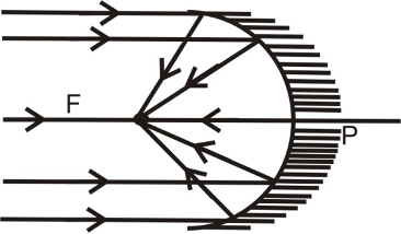
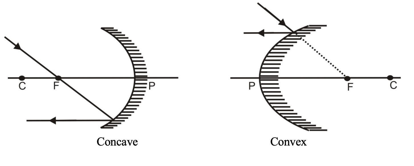
A parallel beam of light after reflectioin from a concave mirror converges at a point in front of the mirror. This point (F) is the focus of a concave mirror it is real. |
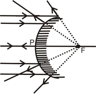
A parallel beam of light after reflectioin from a convex surface diverges and the rays do not meet. However on producing backward, the rays appear to meet at a point behind the mirror. This point is focus of the convex mirror and it is virtual. |
RELATION BETWEEN RADIUS OF CURVATURE AND FOCAL LENGTH OF A SPHERICAL MIRROR:
For spherical mirror having small aperture, the principal focus ‘F’ lies exactly at the mid point of the pole P and the centre of curvature C as shown in the figure 12 & 13. Therefore the focal length of a spherical mirror (concave or convex) is equal to half of its radius of curvature.
i.e. f = R/2 ⇒ R = 2f
CONCAVE AND CONVEX MIRROR:
Convex mirror is a spherical mirror, whose inner (cave type) surface is silvered and reflection takes place at the outer (convex) surface.
Concave mirror is a spherical mirror, whose outer bulged surface is silvered and reflection takes place from the inner hollow (cave type) surface.
Rules for the formation of images by concave & convex mirrors:
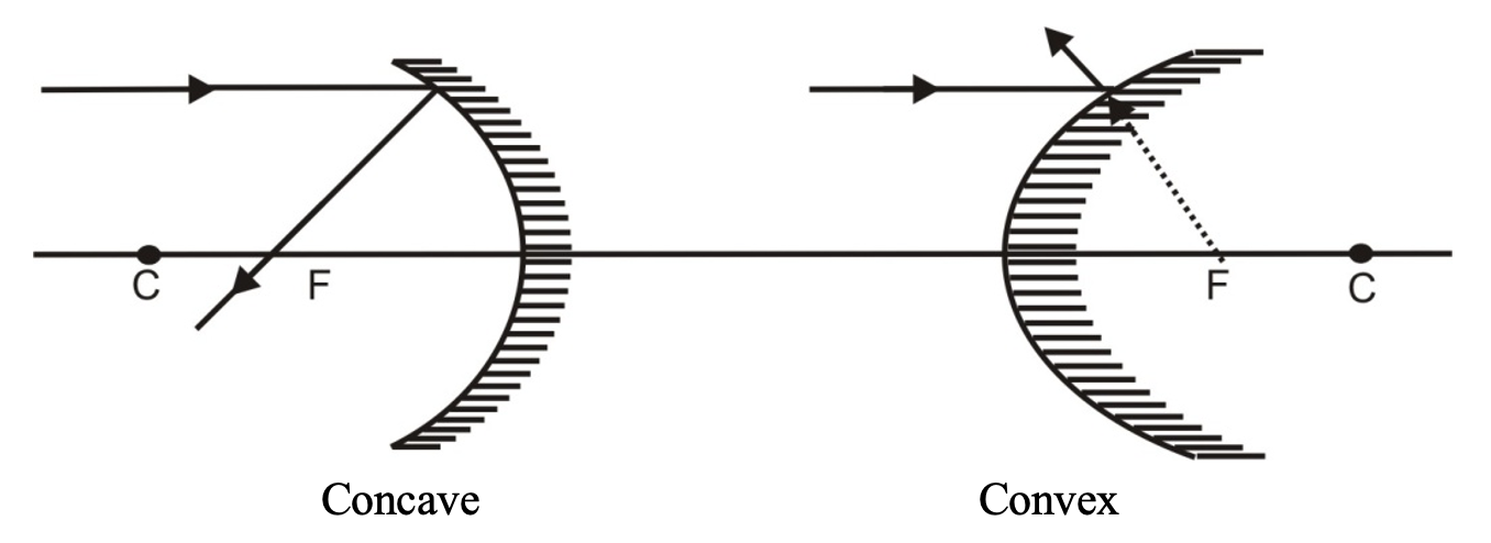
(i) A ray incident parallel to the principal axis actually passes (concave) or appears to pass (convex) through the focus.
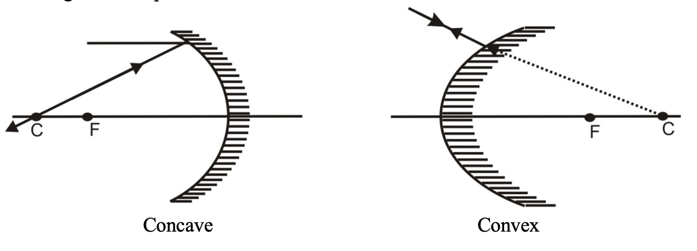
(ii) A ray incident through the centre of curvature (C) falls normally and is reflected back along the same path.
(iii) A ray incident through the focus is reflected parallel to the principal axis.
FORMATION OF DIFFERENT TYPES OF IMAGES BY A CONCAVE MIRROR IN DIFFERENT POSITIONS OF THE OBJECT:
The type of image formed by a concave mirror primarily depends on the position of the object in front of the mirror. When an object is moved closer to the mirror, starting from infinity, the following six cases arise:
(i) When the object is at infinity
When the object is at infinity, the rays of light starting from the object on travelling such a large distance are assumed to become parallel to each other while falling on the mirror. These parallel rays of light may fall on the mirror in the following two ways.
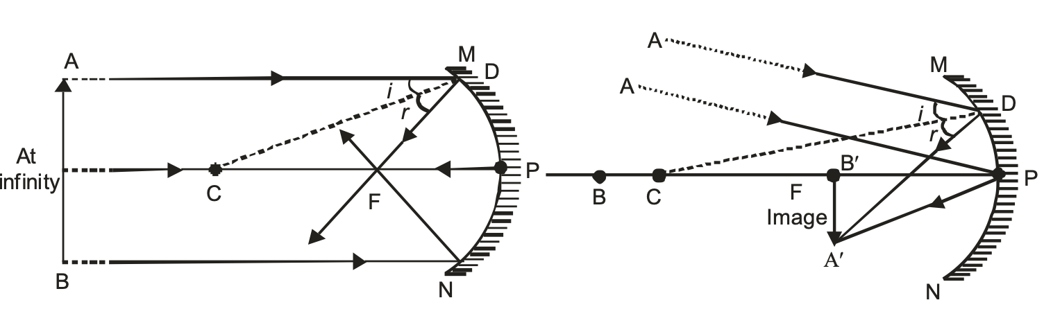
In the above two cases image is formed at the focus of the mirror. Therefore we can say that when the object is at infinity. The image is:
(a) Formed at the focus ‘F’ of the mirror.
(b) Real and inverted.
(c) Highly diminished, point sized.
(ii) When the object is beyond the centre of curvature ‘C’ of concave mirror
When the object is placed beyond the centre of curvature ‘C’ of the concave mirror, the image is
(a) Formed between the Focus ‘F’ and the centre of curvature ‘C’ of the concave mirror.
(b) Real and inverted.
(c) Smaller in size and diminished.
(iii) When the object is at the centre of curvature of concave mirror
When the object is placed at the centre of curvature of concave mirror. The image is
(a) Formed at the centre of curvature ‘C’ of the concave mirror.
(b) Real and inverted.
(c) Of the same size as that of the object.
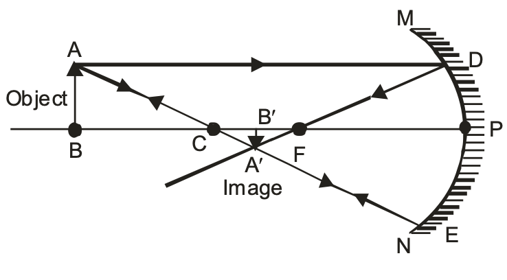
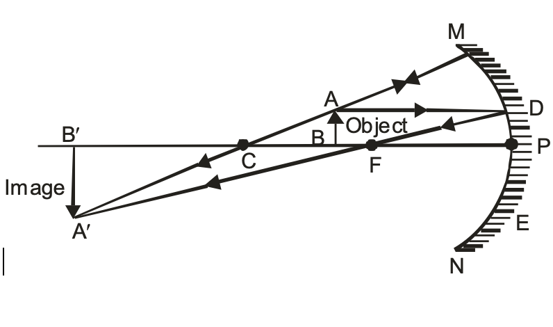
(iv) When the object is placed between the centre of curvature ‘C’ and Focus ‘F’ of concave mirror
When the object is placed between the centre of curvature ‘C’ and Focus ‘F’ of concave mirror. The image is:
(a) Formed beyond centre of curvature ‘C’ of concave mirror
(b) Real and inverted.
(c) Enlarged, i.e. Larger in size than the object.
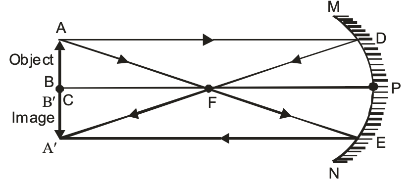
(v) When the object is at the Focus ‘F’ of a concave mirror
When the object is placed at the focus ‘F’ of a concave mirror. The image is
(a) Formed at infinity.
(b) Real and inverted.
(c) Highly enlarged, magnified.
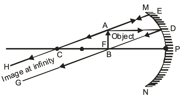
Image formation by a concave mirror for different positions of the object:
| Position of the Object | Position of the image | Size of the image | Nature of the image |
| At infinity | At the focus F | Highly diminished, point-sized | Real and inverted |
|
Beyond C |
Between F and C |
Diminished |
Real and inverted |
|
At C |
At C |
Same size |
Real and inverted |
|
Between C and F |
Beyond C |
Enlarged |
Real and inverted |
|
At F |
At infinity |
Highly enlarged |
Real and inverted |
|
Between P and F |
Behind the mirror |
Enlarged |
Virtual and erect |
USES OF CONCAVE MIRROR:
(i) They are used as shaving mirrors.
(ii) They are used as reflectors in car head-lights, search lights, torches and table lamps.
(iii) They are used by doctors to concentrate light on body parts like ears and eyes which are to be examined.
(iv) Large concave mirrors are used in the field of solar energy to focus sun-rays on the objects to the heated.
METHOD TO FIND OUT THE APPROXIMATE FOCAL LENGTH OF A CONCAVE MIRROR:
To find out the approximate focal length of a concave mirror, focus a distant object (at infinity) on a screen by using a concave mirror whose focal length is to be determined. The sharp image of this object will be formed at the focus of the concave mirror. The distance of the image so formed from the concave mirror is equal to the focal length of concave mirror. Measure this distance with the help of a scale. It will give us the approximate focal length of the concave mirror.
FORMATION OF DIFFERENT TYPES OF IMAGES BY A CONVEX MIRROR IN DIFFERENT POSITIONS OF THE OBJECT:
The type of image formed by a convex mirror primarily depends upon the position of the object in front of the mirror. When an object is moved closer to the mirror, starting from infinity, the following two cases arise:
(i) When the object is at infinity
When the object is at infinity, the rays of light starting from the object on travelling such a large distance are assumed to become parallel to each other while falling on the mirror. These parallel rays of light may fall on the mirror in the following two ways
(a) All the incident rays become parallel to the principal axis of the convex mirror.
(b) All the incident rays falling obliquely to the principal axis.
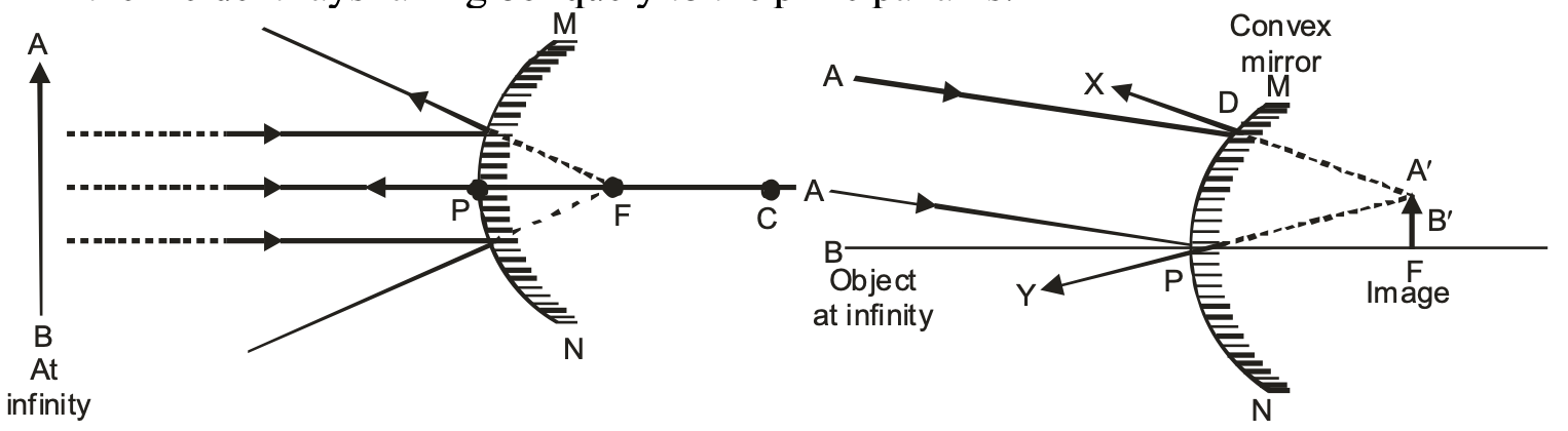
In the above two cases image is formed at the Focus ‘F’ of the convex mirror, behind the mirror.
Therefore, we can say that when the object is at infinity, the image is formed
(a) At the Focus ‘F’ behind the mirror.
(b) Virtual and erect.
(c) Highly diminished, point sized (much smaller than the object).
(ii) When the object is at finite distance from the convex mirror. i.e. between infinity and the pole P of the convex mirror :
When the object is at finite distance i.e. anywhere between infinity and the pole ‘P’ of the convex mirror. The image is formed
(a) Between the pole ‘P’ and Focus ‘F’ behind the convex mirror.
(b) Virtual and erect.
(c) Diminished, smaller than the object.
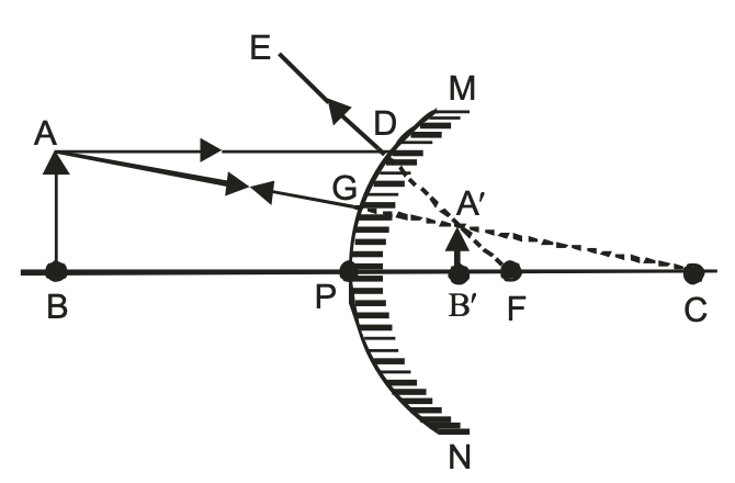
Image formation by a convex mirror for different positions of the object:
| Position of the Object | Position of the image | Size of the image | Nature of the image |
| At infinity | At the focus F, behind the mirror | Highly diminished, point-sized | Virtual and erect |
| Between infinity and the pole P of the mirror | Between P and F, behind the mirror | Diminished | Virtual and erect |
USES OF CONVEX MIRROR:
Some of the practical uses of convex mirrors are:
(i) A convex mirror is used as a reflector in street lamps. As a result, light from the lamp diverges over a large area.
(ii) Convex mirrors are used as rear-view mirrors in automobiles (like cars, trucks and buses) to see the objects (traffic) at the rear side.
The convex mirror is preferred as a rear view mirror because:
(a) A convex mirror always produces an erect image of the objects.
(b) The size of the image formed by a convex mirror is highly diminished or much smaller than the object, due to which it covers a wide field of view, which enables the driver to view much larger area of the traffic behind him than would be possible with a plane mirror concave mirror.
METHOD TO DISTINGUISH BETWEEN A PLANE MIRROR, A CONCAVE MIRROR AND A CONVEX MIRROR WITHOUT TOUCHING THEM:
To distinguish between a plane mirror, a concave mirror and a convex mirror, without touching them, we simply look at the image of our face in the three mirrors, turn by turn.
All of them will produce an image of our face but of different types.
A plane mirror will produce virtual and erect image of the same size as our face and we will look our normal self.
A concave mirror will produce a virtual, erect and magnified image of our face i.e. our face will look much bigger.
A convex mirror will produce a virtual, erect but diminished image of our face i.e. our face will look much smaller.
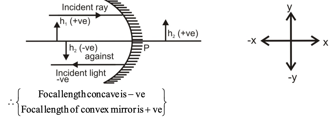
SIGN CONVENTION FOR MEASURING DISTANCE IN CONCAVE & CONVEX MIRROR:
(i) All distances are measured from the pole.
(ii) The incident ray is taken from left to right.
(iii) Distances measured in the same direction as that of the incident ray are taken to be +ve.
(iv) Distances measured in a direction opposite to the incident ray are taken to be -ve.
(v) Distances measured upwards and perpendicular to principal axis are taken +ve.
(vi) Distance measured downwards and perpendicular to principal axis are taken -ve.
IMPORTANT: These signs are according to the rectilinear co-ordinate system.
NOTE: Always draw a rough ray diagram while solving a numerical problem. Otherwise we will be confuse as to which distance should be taken as +ve & which -ve.
For virtual image : M is +ve [as virtual image is erect h1 is + ve as well as h2 is + ve
For real image : m is -ve [as real image is always inverted h2 is – ve while h1 is + ve]
MIRROR FORMULA
Let us first know about the terms used in the mirror formula of spherical mirrors.
(i)Object distance (u) : The distance of the object from the pole ‘P’ of the spherical mirror is called the object distance. It is denoted by the letter ‘u’
(ii) Image Distance (v) : The distance of the image from the pole ‘P’ of the spherical mirror is called the image distance. It is denoted by the letter ‘v’.
(iii)Focal length (f) : The distance of the principal focus (F) from the pole (P) of the spherical mirror is called the focal length. It is denoted by the letter ‘f ‘.
The relationship between the image distance (v), object distance (u) and focal length (f ) of a spherical mirror is known as the mirror formula. The Mirrorformula can be written as :
1/image distance + 1/object distance = 1/focal length
Symbolically = 1/v + 1/u = 1/f
where the symbols have their usual meaning.
POWER OF MIRROR:
A spherical mirror has infinite number of focus. Optical power of a mirror (in Dioptres)
= – 1/f(in meters)
LINEAR MAGNIFICATION PRODUCED BY MIRRORS
The linear magnification produced by a spherical mirror (concave or convex) is defined as the ratio of the height of the image (h') to the height of the object (h). It is a pure ratio and has no units. It is denoted by the letter 'm' and is given by
linear magnification (m) = height of the image (h')/height of the object (h)
or m = h'/h
The linear magnification 'm' is also related to the object distance (u) and image distance (v). It can be expressed as :
Linear Magnification, m = -v/u
⇒ Linear magnification, m = h'/h = -v/u
This shows that the linear magnification produced by a mirror is also equal to the ratio of the image distance (v) to the object distance (u) with a minus sign.
IN CASE OF CONCAVE MIRROR:
(i) For real and inverted image: According to the New Cartesian Sign Convention, for the real and inverted images formed by a concave mirror,
object height (h) is always +ve.
image height (h') is always -ve.
∴ Linear magnification, m = h'/h
m = -ve/+ve or m = -ve.
(ii) For virtual and Erect image: According to the New Cartesian Sign Convention, for the virtual and erect images formed by a concave mirror,
object height (h) is always +ve.
image height (h') is always +ve.
∴ Linear magnification, m = h'/h
m = +ve/+ve or m = +ve.
IN CASE OF CONVEX MIRROR:
A convex mirror always forms a virtual and erect image.
(i) For virtual and erect image : According to the New Cartesian Sign Convention, for the virtual and erect images formed by a convex mirror,
Object height (h) is always +ve.
Image height (h') is always +ve.
∴ Linear magnification, m = h'/h
or m = +ve/+ve
or m = +ve.
FOR SPHERICAL MIRRORS IF THE: (i) Linear magnification, m > 1 the image is enlarged i.e. greater than the object (ii) Linear magnification, m = 1 the image is of the same size as the object. (iii) Linear magnification, m < 1 The image is diminished i.e. the image is smaller than the object.
SOME IMPORTANT CONCLUSIONS
On the basis of the New Cartesian Sign Convention discussed above, we can draw the following conclusions for the spherical mirrors (concave as well as convex mirrors).
IN THE CASE OF CONCAVE MIRROR:
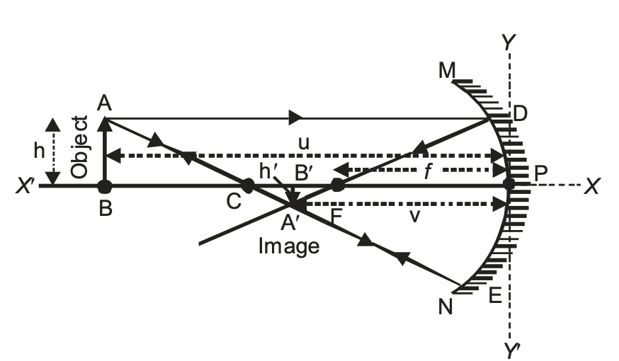
(i) For real and inverted image
Focal length (f) = −ve Radius of curvature (R) = −ve Object distance (u) = −ve Object height (h) = +ve Image distance (v) = −ve Image height (h') = −ve Magnification (m) = −ve
[The image also contains a ray diagram showing a concave mirror with labeled points A, B, C (center), P (pole), M, D, E, N, and shows the formation of a real inverted image A'B' below the principal axis X-X'. The diagram includes the object AB above the axis and various ray paths.]
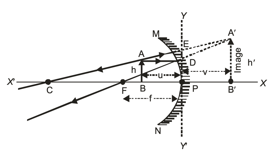
(ii) For virtual and erect image
focal length (f) = -ve Radius of curvature (R) = -ve Object distance (u) = -ve Object height (h) = +ve Image distance (v) = +ve Image height (h') = +ve Magnification (m) = +ve
The image also shows a ray diagram on the right side with:
- A convex mirror (shown with hatched lines)
- Points labeled: A, B, C, F, P, M, N, E, D
- Image points: A', B'
- Heights marked as h and h'
- Distances marked as u, v, and f
- Principal axis marked as X-X'
- Y-Y' axis perpendicular to the principal axis
- Ray paths shown with solid and dashed lines
- The object AB and its virtual erect image A'B'
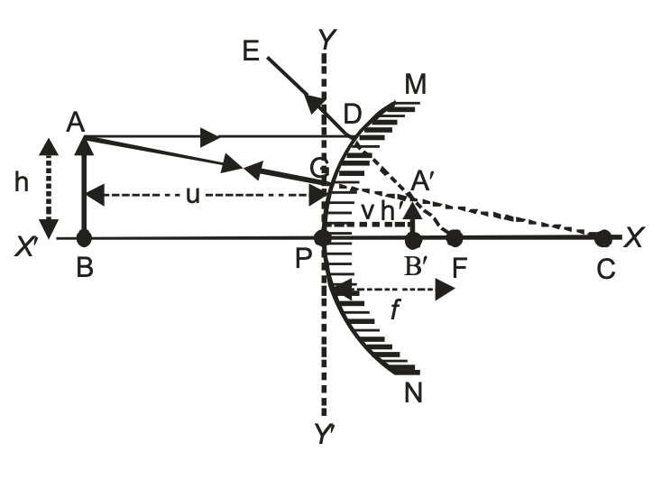
IN CASE OF CONVEX MIRROR
convex mirror always forms a virtual and erect image.
Therefore for virtual and erect image:
Focal length (f) = +ve
Radius of curvature (R) = +ve
Object distance (u) = –ve
Object height (h) = +ve
Image distance (v) = +ve
Image height (h¢) = +ve
REFRACTION OF LIGHT
When light travels in the same homogeneous medium it travels along a straight path. However, when it passes from on transparent medium to another, the direction of its path changes at the interface of the two media. This is called refraction of light.
The phenomenon of the change in the path of the light as it passes from one transparent medium to another is called refraction of light. The path along which the light travels in the first medium is called incident ray and that in the second medium is called refracted ray. The angles which the incident ray and the refracted ray make with the normal at the surface of separation are called angle of incidence (i) and angle of refraction (r) respectively.
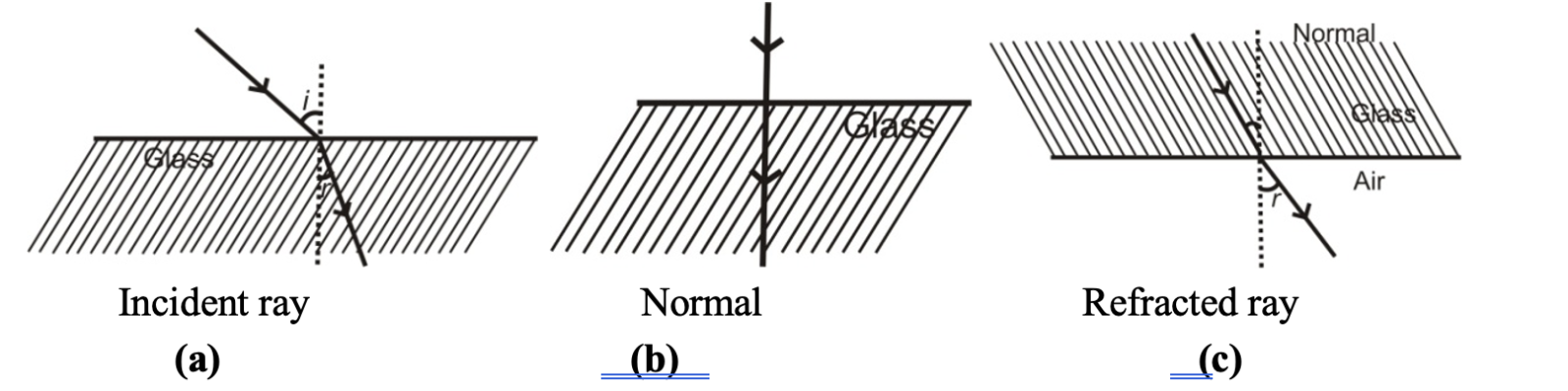
It is observed that:
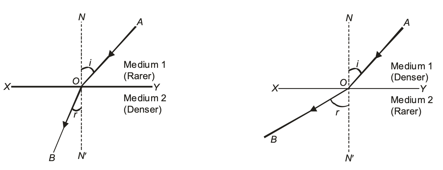
(i) When a ray of light passes from an optically rarer medium to a denser medium it bends towards the normal (∠r < ∠i), as shown in figure (a).
(ii) When a ray of light passes from an optically denser to a rarer medium it bends away from the normal (∠r > ∠i) as shown in figure (b).
(iii) A ray of light traveling along the normal passes undeflected, as shown is figure (c). Here ∠i = ∠r = 0°.
Cause of Refraction:
We come across many media like air, glass, water etc. The medium we study are usually transparent material through which the light is transmitted. Every transparent medium has a property known as optical density. The optical density of a transparent medium is closely related to the speed of light in the medium. If the optical density of a transparent medium is low, then speed of light in that medium is high. Such a medium is known as an optically rarer medium. Thus, optically rarer medium is that medium through which light travels fast. In other words, a medium in which speed of light is more is known as optically rarer medium.
On the other hand, if the optical density of transparent medium is high, then the speed of light in that medium is low. Such a medium is known as an optically denser medium. Thus, optically denser medium is that medium through which light travels slow. In other words, a medium is which speed of light is less is known as optically denser medium.
Speed of light in air is more than the speed of light in water, so air is optically rarer medium as compared to the water. In other words, water is optically denser medium as compared to air. Similarly, speed of light in water is more that the speed of light is glass, so water is optically rarer medium as compared to the glass. In other words, glass is optically denser medium as compared to water.
When light goes from air (optically rarer medium) to glass (optically denser medium) such that the light in air makes an angle with the normal to the interface separating air and glass, then it bends from its original direction of propagation. Similarly, if light goes from glass to air, again it bends from its original direction of propagation. The phenomena of bending of light from its path is known as refraction. We have seen that the speed of light in different media is different, so we can say that refraction of light takes place because the speed of light is different in different media. Thus, the cause of refraction can be summarized as follows:
(i) Refraction is the deviation of light when it crosses the boundary between two different media (of different optical densities) and there is a change in both the wavelength and the speed of light.
(ii) The frequency of the refracted ray remains unchanged.
(iii) The intensity of the refracted ray is less than that of the incident ray. It is because there is partial reflection and absorption of light at the interface.
Effects of refraction of Light:
(i) If a straight stick is partially put in water, it appears to be bent.
(ii) If we see a water tank its bottom appears to e raises. It also appears to be concave shaped although it is flat.
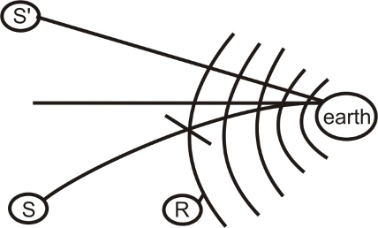
(iii) The sun is visible a few minutes earlier than it actually rises above horizon, because as we go up from earth, the density of air layer decrease, then rays from sun keep on bending towards normal till it enters the eye.
Sun appears to be at S’. For the same reason it keeps on appearing two minutes after sun-set. Hence the day i.e. the time between the sunrise & sunset becomes four minutes longer. The day therefore gets longer by 4 minutes.
(iv) Twinkling of stars:
On a clear night, you might have observed the twinkling of a star, which is due to an atmospheric refraction of star light. The density of the atmosphere, as we know goes on decreasing as the distance above the sea level increase. For the snake of simplicity, air can be supposed to be made up of a very large number of layers show density of which decreases with the distance above the surface of the earth. Therefore, the light from a heavenly body, such as a star, goes on gradually bending towards normal as it travels through the earth’s atmosphere. As the object is always seen in the direction of the light reaching the observer’s eye, the star appears higher up in the sky than its actual position. Further, the densities of the various lavers go on varying due to the convection current set up in air by temperature differences. Thus, the refractive index of layer of air at a particular level goes on changing.
Due to these variations in the refractive indices of the various layers of air, the light from a star passing through the atmospheric air changes its path from time to time and therefore, the amount of light reaching the eye is not always the same. This increase and decrease in the intensity of light reaching the eye results in a change in apparent position or twinkling of the star.
LAWS OF REFRACTION:
Refraction of light occurs according to certain laws, known as the laws of refraction. The following are the two laws of refraction:
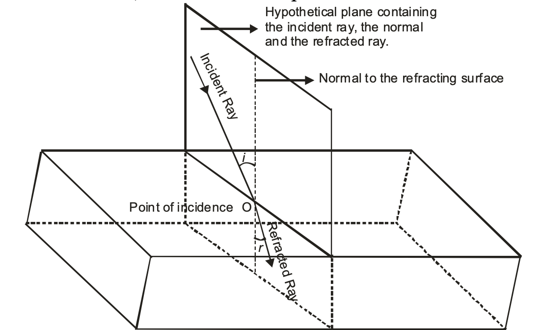
(i)First law of refraction of light: According to the first law of refraction of light, “The incident ray, the refracted ray and the normal to the interface of two transparent media at the point of incidence, all lie in the same plane.”
(ii) Second law of refraction: According to the second law of refraction, "The ratio of sine of angle of incidence to the sine of angle of refraction is a constant, for the light of a given colour (wavelength) and for the given pair of media." This law is also known as Snell's law of refraction.
i.e., sin i/sin r = constant
where i = angle of incidence r = angle of refraction.
This constant value is called the refractive index of the second medium with respect to the first.
REFRACTIVE INDEX:
(a) Refractive Index in terms of Speed of Light:
The refractive index of a medium may be defined in terms of the speed of light as follows:
The refractive index of a medium for a light of given wavelength may be defined at the ratio of the speed of light in vacuum to its speed in that medium.
Refractive index = Speed of light in vacuum/Speed of light in medium
or μ = c/v
Refractive index of medium with respect to vacuum is also called absolute refractive index.
(b) Refractive Index in terms of Wavelength:
Since the frequency (ν) remain unchanged when light passed from one medium to another, therefore,
μ = c/v = (λ_vac × v)/(λ_med × v) = λ_vac/λ_med
The refractive index of a medium may be defined as the ratio of wavelength of light in vacuum to its wavelength in that medium.
(c) Relative Refractive Index: The relative refractive index of medium 2 with respect to medium 1 is defined as the ratio of speed of light (v₁) in the medium 1 to the speed of light (v₂) in medium 2 and is denoted by ₁μ₂.
Thus, ₁μ₂ = v₁/v₂ = λ₁/λ₂ = μ₂/μ₁
As refractive index is the ratio of two similar physical quantities, so it has no unit and dimension.
Factors on which the refractive index of a medium depends are as follows: (i) Nature of the medium. (ii) Wavelength of the light used. (iii) Temperature. (iv) Nature of the surrounding medium
It may be note that refractive index is a characteristic of the pair of the media and also depends on the wavelength of light, but is independent of the angle of incidence.
Physical significance of refractive Index:
The refractive index of a medium gives the following two information’s:
(i) The value of refractive index gives information about the direction of bending of refracted ray. It tells whether the ray will bend towards or away from the normal.
(ii) The refractive index of a medium is related to the speed of light. It is the ratio of the speed of light in vacuum to that in the given medium. For example, refractive index of glass is 3/2. This indicates that the ratio of the speed of light in glass to that in vacuum is 2 : 3 or the speed of light in glass is two-third of its speed in vacuum.
The absolute refractive index of some material media are as follows:
Table: Absolute refractive index of some material media
| Material medium | Refractive index | Material medium | Refractive index |
| Air | 1.0003 | Canada Balsam |
1.53 |
|
Ice |
1.31 |
Rock salt |
1.54 |
|
Water |
1.33 |
Carbon disulphide |
1.63 |
|
Alcohol |
1.36 |
Dense flint glass |
1.65 |
|
Kerosene |
1.44 |
Ruby |
1.71 |
|
Fused quartz |
1.46 |
Sapphire |
1.77 |
|
Turpentine oil |
1.47 |
Diamond |
2.42 |
|
Benzene |
1.50 |
Crown glass |
1.52 |
OPTICAL DENSITY
In the comparison of two media, the medium, or substance having higher refractive index or in which the speed of light is less is called an optically denser medium. On the other hand, a medium (or substance) having lower refractive index or in which the speed of light is higher is called an optically rarer medium.
For example, between the two media, glass and water, glass having a higher refractive index is an optically denser medium than water which has a lower refractive index and hence is an optically rarer medium.
OPTICAL DENSITY VS. MASS DENSITY:
Optical density of a substance is different from its mass density. A medium (substance) may have higher optical density than another medium (substance) but its mass density may be lesser. For example oils (Kerosene, Mustard etc.) having a higher refractive index has higher optical density than water which has a lower refractive index, but the mass density of oils (Kerosene, Mustard etc.) is less than that of water, that is why the oils generally float on the water surface.
THE DIRECTION OF BENDING OF LIGHT:
The two rules which give the direction of bending of a ray of light when it goes from one medium to another are as follows :
(i) When a ray of light goes from a rarer medium to a denser medium, it bends towards the normal at the interface of the two media.
(ii) When a ray of light goes from a denser medium to a rarer medium, it bends away from the normal at the interface of the two media.
Refractive Index in terms of apparent depth and real depth:
Whenever we observe the bottom of a swimming pool or a tank of clear water, we find that the bottom appears to be raised i.e., the apparent depth is less as compared to its real depth.
The extent to which the bottom appears to be raised depends upon the value of refractive index of the refracting medium.
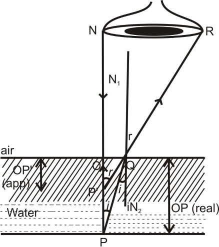
In above fig., ∠PQN₂ = ∠i & ∠N₁QR = ∠r
∴ ᵩμₐ = sin i/sin r
Or ∴ ₐμw = sin r/sin i ............(1)
As ∠N₁QR = ∠OP'Q = ∠r (corresponding angles)
In ΔOP'Q sin r = ∠OP'Q = OQ/P'Q ............(2)
And ∠i = ∠PQN₂ = ∠QPO (alt. Int.(∠s))
∴ In ΔQOP, sin i = sin ∠OPQ = OQ/PQ ............(3)
So from (1) using (2) & (3)
ₐμw = (OQ/PQ)/(OQ/P'Q) = P'Q/PQ ............(4)
Given ∠I is very small, it is nearly normal direction of viewing. PQ ≅ PO & P'Q ≅ P'O ∴ from (4)
ₐμw = PO/P'O ⇒ ₐμw = Real depth/Apparent depth.
Refraction and Speed of Light:
The refraction of light occurs because light has different speed in different media. Speed of light is maximum in vacuum or air. It is less in any other medium. Denser in the medium lesser is the speed of light. Refractive index of a medium depends not only on its nature and physical conditions, but also on the colour or wavelength of light. It is more for violet light and less for red light (VIBGYOR).
To find refractive index of two media w.r.t. each other when their refractive indices w.r.t. air are given. A ray of light AB refracts from different medium as shown in figure below.
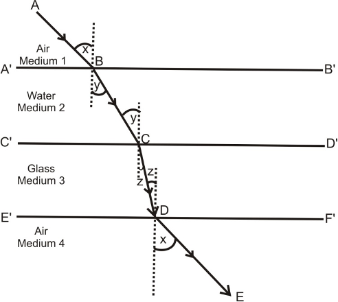
(i) For refractive index at interface A'B'
ₐμw = sin x/sin y ................(i)
(ii) For refractive index at interface C'D'
ₐμg = sin y/sin z ................(ii)
(iii) For refractive index at interface E'F'
gμₐ = sin z/sin x ................(iii)
Multiply (1), (2) & (3)
ₐμw × ₐμg × gμₐ = 1
qμg = 1/(ₐμw × gμₐ)
wμg = ₐμg/ₐμw ................(iv)
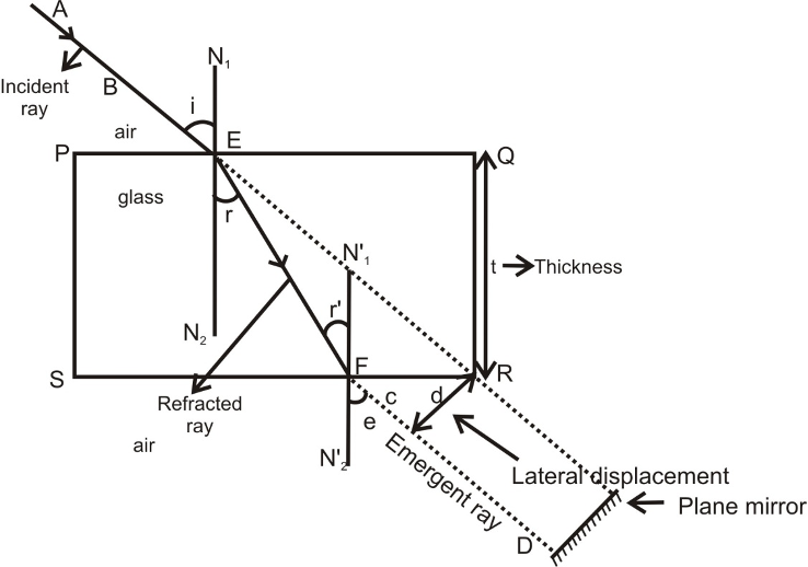
REFRACTION THROUGH A GLASS SLAB(considering no absorption):
Refraction through a rectangular glass slab:
Consider a rectangular glass slab, as shown in the figure. A ray AE is incident on the face PQ at an angle of incidence I. On entering the glass slab, it bends towards normal and travels along EF at an angle of refraction r. The refracted ray EF is incident on face SR at an angle of incidence r’. The emergent ray FD bends away from the normal at an angle of refraction e.
Thus the emergent ray FD is parallel to the incident ray AR, but it has been laterally displaced with respect to the incident ray. There is shift in the path of light on emerging from a refracting medium with parallel faces.
Lateral shift:
Lateral shift is the perpendicular distance between the incident and emergent rays when light is incident obliquely on a refracting slab with parallel faces.
Factors on which lateral shift depends are :
(i) Lateral shift is directly proportional to the thickness of glass slab.
(ii) Lateral shift is directly proportional to the incident angle.
(iii) Lateral shift is directly proportional to the refractive index of glass slab.
(iv) Lateral shift is inversely proportional to the wavelength of incident light.
Lateral shifting of light in glass slab
If a plane mirror is placed in the path of emergent ray FD then the path of the emergent ray along FD is reversed back, it follows the same path along which it was incident i.e. the incidence ray becomes the emergent ray & emergent ray becomes the incident ray. It is known as principle of reversibility of light.
Case - I: For light going from air to glass of point E.
∠i = angle of incident, ∠r angle of refraction.
ₐμg = sini/sinr ................(1) ( ₐμg = absolute refractive index of glass)
Case - II: For light going from glass to air at point F.
⇒ gμₐ = sing/sine where{∠r = angle incidence }∴ ∠r = ∠r' {∠e = angle of refraction}
⇒ gμₐ = sinr/sini (as ∠e = ∠i)
∴ 1/gμₐ = sini/sinr ..............(2)
∴ From (1) & (2)
ₐμg = 1/gμₐ ⇒ [ₐμg × gμₐ = 1].
SPHERICAL LENSES
A lens is a piece of transparent refracting material bounded by two spherical surface or one spherical and other plane surface.
A lens is the most important optical component used in microscopes, telescopes, cameras, projectors etc.
Basically lenses are of two types :
(i) Convex lens or converging lens (ii) Concave lens or diverging lens
Convex lens and its type:
A lens which is thick at the centre and thin at the edges is called a convex lens. The most common form of a convex lens has both the surfaces bulging out to the middle. Some forms of convex lens are shown in the figure.
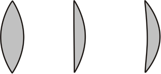
Concave lens and its type:
A lens which is thin at the middle and thick at the edges is called a concave lens. The most common form of a concave lens has both the surfaces depressed inward at the middle. Some forms of concave lenses are shown in the figure.
SOME IMPORTANT TERMS ASSOCIATED WITH SPHERICAL LENSES
OPTICAL CENTRE:
The centre point of a lens is known as its optical centre. It is usually represented by the letter O. A ray of light passing through the optical centre at a lens goes undeviated.
APERTURE:
The effective diameter of the circular outline at a spherical lens is called its aperture. In the figure (a), (b) ‘AB’ is the diameter of the circular outline of the lens which represents aperture of the lens or we can say that aperture is the actual refracting surface of the lens.
CENTRE OF CURVATURE:
A lens, either a convex lens or concave lens, has two spherical surfaces. Each of these surfaces form a part of a sphere. The centres of these spheres are called centres of curvature of the lens. The centre of curvature of a lens is usually represented by the letter C. Since there are two centres of curvature, we may represent them as C1 and C2.
PRINCIPAL AXIS:
An imaginary straight line passing through the two centres of curvature of a lens is called its principal axis.
PRINCIPAL FOCUS AND FOCAL LENGTH OF A CONVEX LENS
PRINCIPAL FOCUS:
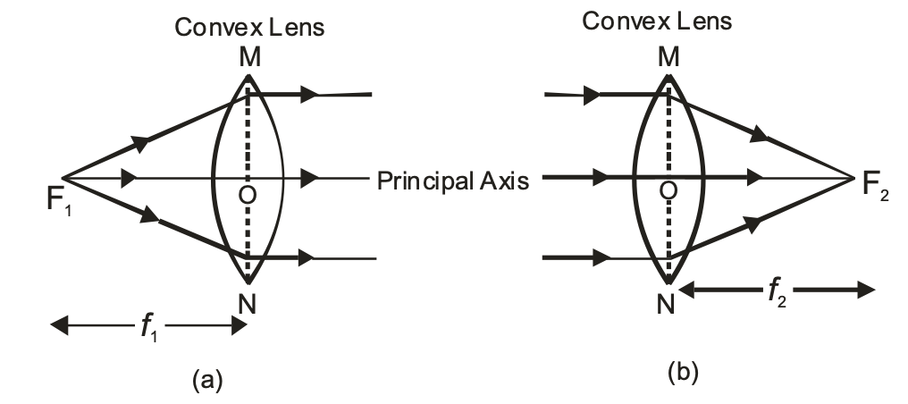
Principal focus of a convex lens is a point on its principal axis to which light rays parallel to the principal axis converge after refraction by the lens. It is usually represented by the letter ‘F’. However a convex lens has two spherical surfaces and hence it has two principal foci or two focal points which are usually denoted by the letters ‘F1’ and ‘F2’ and are known as the first principal focus (F1) and the second principal focus (F2). The two foci of a lens are at equal distances from the optical centre, one on either side of the lens.
Since all the light rays actually pass through the focus (or foci) of a convex lens, therefore, a convex lens has real focus (or foci).
(i) First Principal Focus (F1) : The first principal focus (F1) of a convex lens is the position of a point object on the principal axis of the lens, for which the image is formed at infinity. It is usually denoted by the letter ‘F1’ as shown in the figure (a)
(ii) Second Principal Focus (F2) : The second principal focus (F2) of a convex lens is the position of an image point on the principal axis of the lens, for which the object is situated at infinity. It is usually denoted by the letter ‘F2’ as shown in the figure (b).
FOCAL LENGTH:
The distance of the principal Focus (F1 or F2) from the optical centre ‘O’ of a lens is called its focal length. It is usually denoted by letter ‘f ‘. Since a convex lens has two principal foci, so it has two focal lengths, known as first focal length (f1) and the second focal length (f2).
(i) First Focal length : The distance of the first principal focus of the lens from the optical centre ‘O’ of the lens is called first focal length of convex lens. It is represented by ‘f1’. i.e. OF1 = f1 .
(ii)Second Focal length : The distance of second principal focus of the lens from the optical centre ‘O’ of the lens is called second focal length of convex lens. It is represented by ‘f2’
i.e. OF2 = f2 (figure b).
In a Convex lens f1 = f2
PRINCIPAL FOCUS AND FOCAL LENGTH OF A CONCAVE LENS
PRINCIPAL FOCUS:
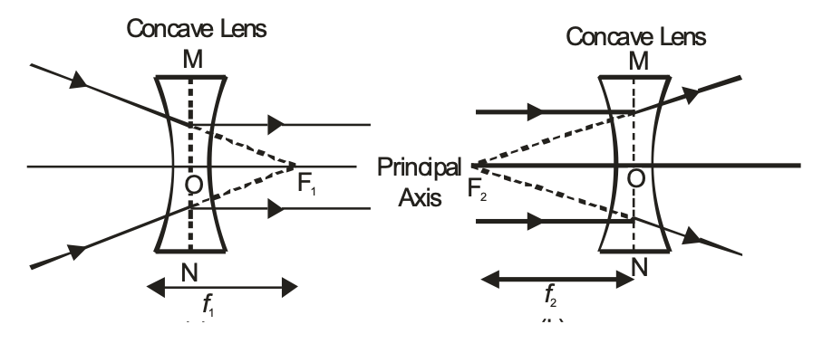
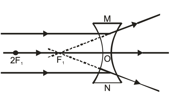
The principal focus of a concave lens is a point on its principal axis from which light rays parallel to the principal axis, appear to diverge after refraction by the lens. It is usually represented by the letter ‘F’. However a concave lens has two spherical surfaces and hence it has two principal foci or two focal points which are usually denoted by the letters ‘F1’ and ‘F2’ and are known as the first principal focus ‘F1’ and the second principal focus ‘F2’. The two foci of a lens are at equal distances from the optical centre, one an either side of the lens.
Since the light rays do not actually pass through the focus (or foci) of a concave lens, therefore, a concave lens has a virtual focus.
(i) First Principal Focus (F1) : The first principal focus (F1) of a concave lens is the virtual position of a point object on the principal axis of the lens, for which the image formed by the concave lens is at infinity. It is usually denoted by the letter ‘F1’, as shown in the figure (a)
(ii) Second Principal Focus (F2): The second principal focus (F2) of a concave lens is the position of image point on the principal axis of the lens, when the object is situated at infinity. It is generally denoted by the letter (F2), as shown in the figure (b).
FOCAL LENGTH:
The distance of the principal focus (F1 or F2) from the optical centre ‘O’ of a lens is called its focal length. It is usually denoted by the letter ‘f ‘. Since a concave lens has two principal foci, so it has two focal lengths, known as : first focal length (f1) and second focal length (f2).
(i)First Focal Length (f1): The distance of first principal focus (F1) of the lens from optical centre ‘O’ of the lens is called first focal length of concave lens. It is represented by ‘F1’. i.e. OF1 = f1. [see (a) in above figure].
(ii) Second Focal Length (F2): The distance of second principal focus (F2) of the lens from the optical centre ‘O’ of the lens is called second focal length of concave lens. It is represented by ‘f2’. i.e. OF2 = f2 [see (b) in above figure].
Rules for the formation of images by Convex Lens:
The positions of the image formed by a convex lens can be found by considering two of the following rays (as explained below).
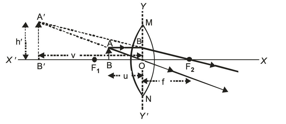
(i) A ray of light coming parallel to principal axis, after refraction through the lens, passes through the principal focus (F) as shown in the figure.
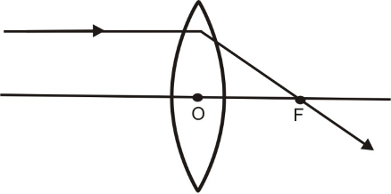
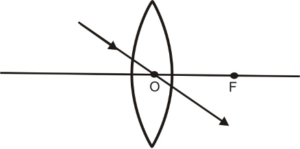
(ii) A ray of light passing through the optical centre O of the lens goes straight without suffering any deviation as shown in the figure.
(iii) A ray of light coming from the object and passing through the principal focus of the lens after refraction through the lens, becomes parallel to the principal axis.
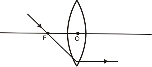
Image formed by Convex Lens:
The position, size and nature of the image formed by a convex lens depends upon the distance of the object from the optical centre of the lens. For a thin convex lens, the various case of image formation are explained below :
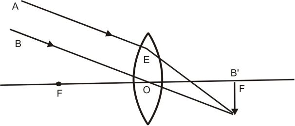
(i) When object at infinity:
When an object lies at infinity, the rays of light coming from the object may be regarded as a parallel beam of light. The ray of light BO passing through the optical centre O goes straight without any deviation. Another parallel ray AE coming from the object, after refraction, goes along EA’ Both the refracted rays meet at A’ in the focal plane of the lens. Hence, a real, inverted and highly diminished image is formed on the other side of the lens in its focal plane.
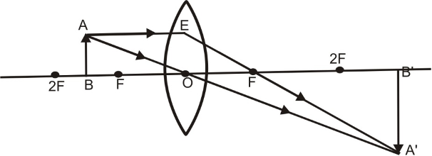
(ii) When object lies beyond 2F:
When the object lies beyond 2F, its real, invert and diminished image is formed between F and 2F on the other side of the lens as explained below:
A ray of light AE coming parallel to the principal axis, after refraction, passes through the principal focus F and goes along EF. Another ray AO passing through the optical centre O goes straight without suffering any deviation. Both the refracted rays meet at A’. Hence, a real, inverted and diminished image is formed between F and 2F on the other side of the convex lens.
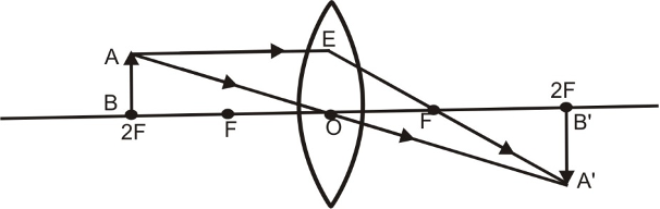
(iii) When object lies at 2F:
When an object lies at 2F, its real & inverted image having same size as that of the object is formed on the other side of the convex lens as explained below :
A ray of light AE coming parallel to the principal axis, after refraction, passes through the principal focus F and goes along EF. Another ray AO passing through the optical centre O goes straight without suffering any deviation. Both the refracted rays meet at A’. Hence a real, inverted image having the same size as the of the object is formed at 2F on the other side of the lens.
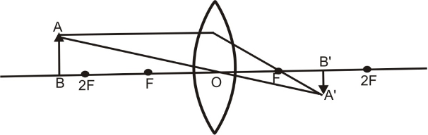
(iv) When object lies between F and 2F.
When an object lies between F and 2F in front of a convex lens, its real, inverted and magnified image is formed beyond 2F on the other side of the lens an explained below:
A ray of light AE coming parallel to the principal axis, after refraction, passes through the principal focus F and goes along EF. Another ray of light AO passing through the optical centre goes straight without any deviation. Both these refracted rays meet at A’. Hence a real, inverted and magnified image is formed beyond 2F on the other side of the lens.
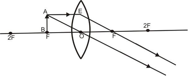
(v) When object lies at F:
When an object lies at the principal focus F of a convex lens, then its real, inverted and highly magnified image is formed at infinity on the other side of the lens as explained below:
A ray of light AE coming parallel to the principal axis, after refraction, passes through the principal focus F and goes along EF. Another ray of light AO passing through the optical centre O goes straight without any deviation. Both these refracted rays are parallel to each other and meet at infinity. Hence, a real, inverted, highly magnified image is formed at infinity on the other side of the lens.
(vi) When object lies between O and F:
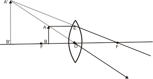
When an object lies between the optical centre O and the principal focus F of a convex lens, then its virtual, erect and magnified image is formed on the same side as that of the object as explained below :
A ray of light AE coming parallel to the principal axis, after refraction, passes through the principal focus F and goes along EF. Another ray of light AO passing through the optical centre goes straight without any deviation. Both these refracted rays appears to meet at A’. When produced backward. Hence a virtual, erect and enlarged image is obtained on the same side of the lens.
The results of image formation by a convex lens are summarised in the table:
|
Position of the object |
Positon of the image |
Size of the image |
Nature of the image |
|
At infinity |
At the focus F |
Highly diminished |
Real and inverted |
|
Beyond 2F |
Between F and 2F |
Diminished |
Real and inverted |
|
At 2F |
At 2F |
Same size |
Real and inverted |
|
Between F and 2F |
Beyond 2F |
Magnified |
Real and inverted |
|
At F |
At infinity |
Highly magnified |
Real and inverted |
|
Between O and F |
On the side of the object |
Magnified |
Virtual and erect |
HOW TO FIND OUT THE APPROXIMATE FOCAL LENGTH OF A CONVEX LENS:
To find out the approximate focal length of a convex lens, focus a distant object (at infinity) on a screen by using a convex lens whose focal length is to be determined. The sharp and inverted image of this object will be formed at the focus of the convex lens. The distance of the image so formed from the convex lens is equal to the focal length of convex lens. Measure this distance with the help of a scale. It will give us the approximate focal length of the convex lens.
RULES FOR TRACING IMAGES FORMED BY CONCAVE LENS:
When an object is placed in front of a concave lens, its image is formed at a point where at least two refracted light rays appear to meet. To trace the position and nature of the image formed by a concave lens, the three rays of light are commonly used, out of which, we take any two rays of light (starting from the object) whose paths, after refraction from the lens are known to us and are easy to draw. We may call them (the three rays) as rules for tracing images in concave lens. These are as follows:
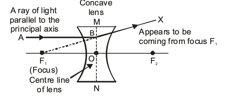
(i) A ray of light which is parallel to the principal axis of a concave lens, appears to be coming from its focus after refraction through the lens, as shown in the figure below.
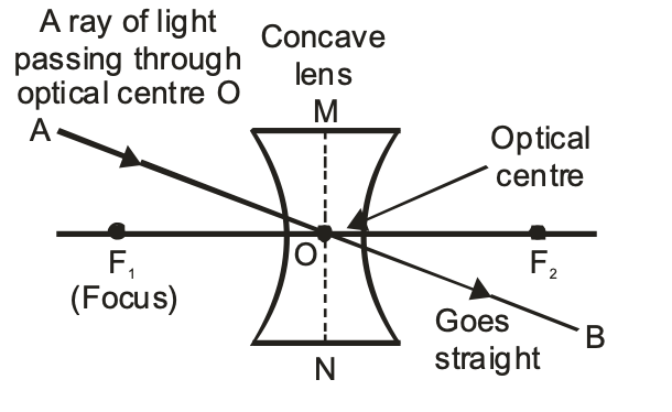
(ii) A ray of light passing through the optical centre ‘O’ of a concave lens goes straight (undeviated) after refraction through the lens, as shown in the figure.
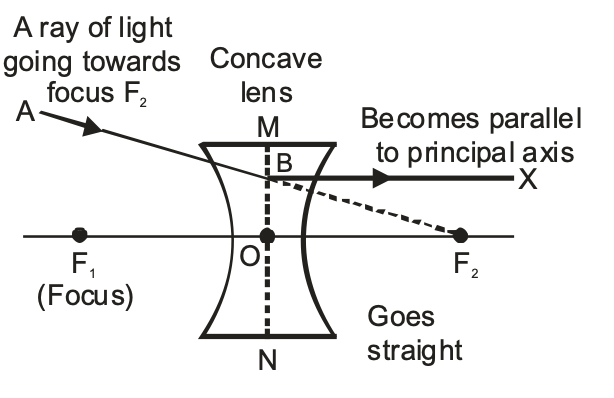
(iii) A ray of light appearing to pass towards the focus of a concave lens, becomes parallel to its principal axis after refraction through the lens, as shown in the figure.
FORMATION OF DIFFERENT TYPES OF IMAGES BY A CONCAVE LENS IN DIFFERENT POSITION OF THE OBJECT:
The type of image formed by a concave lens primarily depends upon the position of the object in front of the lens. When the object is moved closer to the lens, starting from infinity, the following two cases arise.
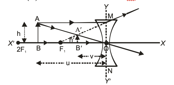
(i) When the object is at infinity: When the object is at infinity all the incident rays of light become parallel to the principal axis of the concave lens and appear to be coming from its focus after refraction through the lens. Hence the image formed is-
(a) At focus F1 (on the same side of the lens as the object).
(b) Virtual and erect.
(c) Highly diminished, point sized.
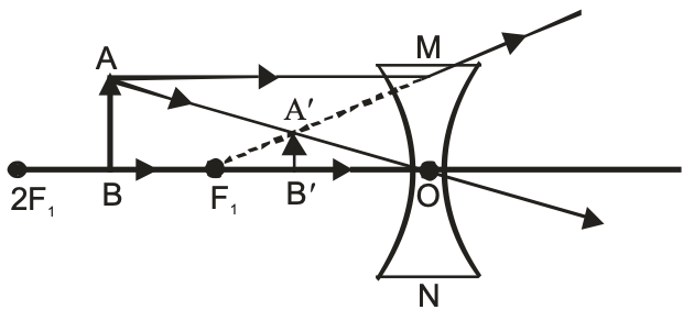
(ii) When the object is placed between infinity and optical centre ‘O’ of the concave lens: When the object is placed anywhere between the infinity and the optical centre ‘O’ of the concave lens, the image formed is-
(a) Between focus (F1) and optical centre ‘O’ (on the same side of the lens as the object).
(b) Virtual and erect.
(c) Diminished (smaller than the object).
Nature, position and size of the image formed by a concave lens for various positions of the object:
| Position of the Object | Position of the image | Size of the image | Name of the image |
| At infinity | At focus F1 | Highly diminished, point-sized | Virtual and erect |
| Between infinity and optical centre O of the lens | Between focus F1 and optical centre O | Diminished | Virtual and erect |
METHOD TO DISTINGUISH BETWEEN A CONVEX LENS AND A CONCAVE LENS WITHOUT TOUCHING THEM:
To distinguish between a convex lens and a concave lens without touching them keep the two lenses close to the page of a book and look for image of the writing on the page through the lens. If the writing (letters) of the book appears enlarged, the lens is convex, and if the writing (letters) appears diminished, then it is a concave lens.
This is because, when an object is within the focus of a convex lens, it produces an enlarged image, whereas a concave lens produces a diminished image for all positions of the object.
SIGN CONVENTION FOR REFRACTION BY SPHERICAL LENSES
The New Cartesian Sign Convention is used for measuring the various distances in the ray-diagrams of spherical lenses (convex as well as concave spherical lenses).
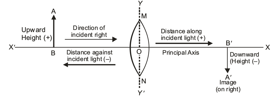
According to the New Cartesian Convention.
(i) The optical centre ‘O’ of the lens is taken as the origin and the principal axis of the lens is taken as the x-axis of the co-ordinate system.
(ii) The object is always placed to the left of the lens i.e. the light (incident rays) from the object falls on the lens from the left hand side.
(iii) All the distances parallel to the principal axis of the spherical lenses are measured from the optical centre ‘O’ of the lenses.
(iv) All the distances measured to the right of the origin (along +ve x-axis) are taken as positive.
(v) All the distances measured to the left of the origin (along –ve x-axis) are taken as negative.
(vi) The distances (heights) measured upwards (i.e. above the x-axis) and perpendicular to the principal axis of the lens are taken as positive.
(vii) The distances (heights) measured downwards (i.e. below the x-axis) and perpendicular to the principal axis of the lens are taken as negative. The following figure illustrates all the points of the New Cartesian. Sign Convention stated above
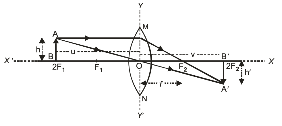
LENS FORMULA
The relationship between the image distance (v), object distance (u) and focal length (f) of a spherical lens is known as the lens formula. The lens formula can be written as :
1/image distance - 1/object distance =1/focal length
Symbolically, 1/u - 1/v = 1/f where the symbols have their usual meaning.
LINEAR MAGNIFICATION PRODUCED BY LENSES
The linear magnification produced by a spherical lens (convex or concave) is defined as the ratio of the height of the image (h') to the height of the object (h). It is a pure ratio and has no units. It is denoted by the letter 'm' and is given by,
Linear magnification (m) = height of the image (h')/height of the object (h)
or m = h'/h - 1
The linear magnification (m) is also related to the object distance (u) and image distance (v).
It can be expressed as: m = v/u.
⇒ Linear magnification, m = h'/h = v/u.
This shows that linear magnification produced by a lens is also equal to the ratio of the image distance (v) to the object distance (u).
IN CASE OF A CONVEX LENS:
(i) For real and inverted image: According to the New Cartesian Sign Convention, for real and inverted images formed by a convex lens,
Object height (h) is always +ve
Image height (h') is always -ve
∴ Linear magnification, m = h'/h
or m = -ve/+ve or m = -ve
(ii) For virtual and erect image: According to the New Cartesian Sign Convention, for the virtual and erect images formed by a convex lens,
Object height (h) is always +ve
Image height (h') is always +ve
∴ Linear magnification, m = h'/h
or m = +ve/+ve
or m = +ve
IN CASE OF A CONCAVE LENS:
A concave lens always form a virtual and erect image.
(i) For virtual and erect image: According to the new Cartesian sign convention, for the virtual and erect images formed by a concave lens,
Object height (h) is always +ve
Image height (h') is always +ve
∴ Linear magnification, m = h'/h
or m = +ve/+ve
or m = +ve
FOR SPHERICAL LENSES:
(i) If linear magnification, m > 1, then the image is enlarged i.e., bigger than the object.
(ii) If linear magnification, m = 1, then the image is of the same size as the object.
(iii) If linear magnification, m < 1 the image is diminished i.e., the image is smaller than the object.
(iv) If the magnification ‘m’ is +ve the image is virtual and erect. And if the magnification ‘m’ is –ve the image will be real and inverted.
SOME IMPORTANT CONCLUSIONS
On the basis of the New Cartesian Sign Convention discussed above, we can draw the following conclusions for the spherical lenses (convex as well as concave lenses).
IN CASE OF CONVEX LENS:
(i) For real and inverted image
Focal length (f ) = +ve
Object distance (u) = –ve
Object height (h) = +ve
Image distance (v) = +ve
Image height (h¢) = –ve
Magnification (m) = –ve
(ii) For virtual and erect image
Focal length (f ) = +ve
Object distance (u) = –ve
Object height (h) = +ve
Image distance (v) = –ve
Image height (h¢) = +ve
Magnification (m) = +ve
IN CASE OF CONCAVE LENS:
Since a concave lens always forms virtual and erect image therefore
For virtual and erect image
Focal length (f ) = –ve
Object distance (u) = –ve
Object height (h) = +ve
Image distance (v) = –ve
Image height (h¢) = +ve
Magnification (m) = +ve
POWER OF A LENS
The power of a lens is the degree of convergence or divergence of light rays achieved by a lens.
The power of a lens is defined as the reciprocal of its focal length in meters. It is denoted by the letter P.
i.e. Power of a lens = 1/(focal length of the lens (in meters))
or P = 1/(f (in meters))
where P = power of a lens and f = focal length of the lens in meters.
The S.I. unit of power is dioptre. It is denoted by the letter 'D'.
One dioptre is the power of a lens whose focal length is 1 metre.
The power of a lens is measured by an instrument called dioptre meter.
A convex lens has positive focal length so the power of a convex lens is positive.
A concave lens has a negative focal length, so the power of a concave lens is negative.
Since the power of a lens is inversely proportional to its focal length P = 1/f(in meters) Therefore, a lens of short focal length has more power than a lens of long focal length (i.e. shorter the focal length, more is the power and vice-versa).
Power of a combination of lenses
If a number of lenses are placed in close contact, then the power of the combination of lenses is equal to the algebraic sum of the powers of individual lens.
i.e. P = P1 + P2 + P3 + ………
Where P = power of combination of lenses.
P1, P2, P3, ……………… = Powers of individual lens placed close to each other.