Electricity: A Complete Guide to Electric Current, Circuits, and Power
Introduction to Electricity
Electricity has revolutionized modern society over the past several centuries, becoming one of the most convenient and widely used forms of energy worldwide. Its primary advantage lies in efficient transmission electrical energy can be transferred over considerable distances with relatively minimal energy loss, enabling centralized power generation to supply electricity to distributed locations.
Electricity manifests in two fundamental types: static electricity and current electricity. Static electricity involves charges at rest, demonstrated when rubbing a glass rod with silk produces positive charges on the glass and negative charges on the silk. Current electricity, conversely, involves charges in motion the type powering our homes and devices daily.
Electric Charge and Coulomb's Law
Electric charge represents a fundamental property of matter. Experiments conclusively demonstrate two types of electric charges: negative and positive. A critical principle governs their interaction: unlike (opposite) charges attract each other, while like (similar) charges repel. The SI unit of electric charge is the coulomb (C), with one coulomb containing approximately 6 × 10¹⁸ electrons.
Coulomb's Law quantifies the force between two charges: the electrostatic force is directly proportional to the product of the two charges and inversely proportional to the square of the distance between them. This fundamental law governs all electrostatic interactions and forms the foundation for understanding electric fields.
Key properties of electric charge include:
- Conservation: Electric charges cannot be created or destroyed, only transferred
- Additivity: Total charge equals the algebraic sum of individual charges
- Quantization: Charge exists in discrete units (multiples of the electron charge)
Conductors, Insulators, and Semiconductors
Materials exhibit vastly different electrical behaviors based on their atomic structure and electron mobility.
Conductors possess very low electrical resistance, allowing electric charges to flow easily. Metals like silver, copper, and aluminum excel as conductors due to loosely held "free electrons" that move readily throughout the material. Silver is the best conductor, though copper and aluminum are more commonly used in electrical wiring due to cost considerations.
Insulators have infinitely high electrical resistance, preventing charge flow. Glass, rubber, most plastics, paper, dry wood, and mica all function as insulators because electrons remain strongly bound to atomic nuclei with no free electrons available for conduction. Electricians wear rubber gloves precisely because rubber's insulating properties protect against electric shock.
Semiconductors occupy the middle ground, with conductivity between conductors and insulators. Silicon and germanium are prominent semiconductors whose conducting properties change significantly with temperature and impurity concentration characteristics that make them invaluable in modern electronics.
Electric Current: Definition and Measurement
Electric current represents the flow of electric charges (electrons) through a conductor. Quantitatively, current measures the amount of charge passing through a given point per unit time. If charge Q (in coulombs) flows through a conductor in time t (seconds), the current I is defined as:
I = Q/t
The SI unit of current is the ampere (A), named after French scientist André-Marie Ampere (1775–1836). One ampere equals one coulomb per second meaning 1 A of current flows when one coulomb of charge passes through a conductor in one second.
Smaller current units include:
- 1 milliampere (mA) = 10⁻³ A
- 1 microampere (µA) = 10⁻⁶ A
Direction of Electric Current
Historically, before electron discovery, scientists established the conventional current direction as flowing from positive to negative terminal. However, electrons (negatively charged) actually move from negative to positive terminal. This conventional direction persists in circuit analysis, though actual electron flow is opposite.
When a cell or battery connects across a wire's ends, an electric force acts on free electrons, causing directional movement from the negative to positive terminal this constitutes electric current flow.
Electric Potential and Potential Difference
Electric potential represents the electric potential energy per unit charge at a point. Mathematically, it equals work done per unit charge:
V = W/Q
where V is potential (measured in volts), W is work done (joules), and Q is charge (coulombs). One volt equals one joule per coulomb (1 V = 1 J/C), named after Alessandro Volta, the voltaic cell inventor.
Potential difference between two points quantifies the work required to move a unit charge between those points. If bringing charge q from infinity to point A requires work W_A, and to point B requires work W_B, the potential difference is:
V_B - V_A = (W_B - W_A)/q
Potential difference drives current flow electrons move from regions of lower potential to higher potential, analogous to water flowing from high to low pressure. Cells and batteries maintain potential difference through internal chemical reactions, functioning like electrical "pumps" in circuits.
Ohm's Law: The Foundation of Circuit Analysis
Ohm's Law establishes the fundamental relationship between voltage, current, and resistance. At constant temperature, current through a conductor is directly proportional to the potential difference across its ends:
V ∝ I or V = IR
where:
- V = potential difference (volts)
- I = current (amperes)
- R = resistance (ohms, Ω)
The constant of proportionality R represents electrical resistance the opposition to current flow. One ohm is defined as the resistance when one ampere flows through a conductor with one volt across its ends (1 Ω = 1 V/1 A).
Experimental Verification
Ohm's Law can be verified by measuring current and voltage across a nichrome wire with varying applied voltages. Plotting voltage versus current yields a straight line through the origin, with slope equal to resistance. The constant ratio V/I confirms Ohm's Law validity for most conductors at constant temperature.
Resistance: Opposition to Current Flow
Resistance arises from collisions between moving electrons and atoms/ions within a conductor. These collisions create opposition to electron flow, quantified by the relationship:
R = V/I
Resistance depends on several factors:
1. Length (l)
Resistance is directly proportional to conductor length: R ∝ l
2. Cross-sectional Area (A)
Resistance is inversely proportional to cross-sectional area: R ∝ 1/A
3. Material (Resistivity, ρ)
Different materials have characteristic resistivities affecting resistance
4. Temperature
For most metals, resistance increases with temperature
Combining these factors yields:
R = ρl/A
where ρ (rho) represents resistivity or specific resistance a material's characteristic property.
Resistivity
Resistivity is defined such that for a conductor with unit length (1 m) and unit cross-sectional area (1 m²), the resistivity numerically equals the resistance:
ρ = RA/l
The SI unit is ohm-metre (Ω·m). Resistivity depends solely on material nature, not dimensions, making it ideal for comparing materials' electrical properties. Good conductors have low resistivity (silver: 1.6 × 10⁻⁸ Ω·m), while insulators have extremely high resistivity.
Alloys like nichrome, manganin, and constantan possess high resistivities, making them suitable for heating elements and resistors. Nichrome's very high resistivity and oxidation resistance at high temperatures make it ideal for electric irons, heaters, and toasters.
Combination of Resistors
Circuits often require specific resistance values achieved by combining multiple resistors in two fundamental configurations: series and parallel.
Resistors in Series
Resistors connected end-to-end with the same current flowing through each are in series connection. For resistances R₁, R₂, and R₃ in series:
- Same current (I) flows through each resistor
- Total voltage divides across resistors: V = V₁ + V₂ + V₃
- Equivalent resistance: R_eq = R₁ + R₂ + R₃
For n identical resistors R in series: R_eq = nR
Key characteristics:
- Equivalent resistance exceeds any individual resistance
- Current remains constant throughout
- Voltage distributes proportionally to individual resistances
- Analogous to increasing conductor length
Resistors in Parallel
Resistors with common connection points at both ends are in parallel connection. For resistances R₁, R₂, and R₃ in parallel:
- Same voltage (V) across each resistor
- Total current divides among resistors: I = I₁ + I₂ + I₃
- Equivalent resistance: 1/R_eq = 1/R₁ + 1/R₂ + 1/R₃
For n identical resistors R in parallel: R_eq = R/n
For two resistors: R_eq = (R₁ × R₂)/(R₁ + R₂)
Key characteristics:
- Equivalent resistance is less than the smallest individual resistance
- Voltage remains constant across all resistors
- Current distributes inversely proportional to resistances
- Maximum current flows through minimum resistance
Heating Effect of Electric Current (Joule's Law)
When current flows through a conductor, electrons collide continuously with positive ions, transferring kinetic energy as thermal energy. This Joule heating increases the conductor's temperature.
Joule's Law states that heat produced is:
- Directly proportional to current squared: H ∝ I²
- Directly proportional to resistance: H ∝ R
- Directly proportional to time: H ∝ t
Combined: H = I²Rt/J
where J = 4.18 J/cal is Joule's mechanical equivalent of heat.
This heating effect is:
- Desirable in: incandescent lamps, toasters, electric irons, water heaters, room heaters
- Undesirable in: electric motors, generators, transformers (causes energy loss)
Tungsten filament lamps operate at approximately 2700°C, converting electrical energy into both heat and light.
Electric Energy and Power
Electric Energy
Electric energy represents the total work done to maintain current flow through a circuit:
W = VIt = I²Rt = V²t/R
The SI unit is the joule (J), but commercial billing uses the kilowatt-hour (kWh):
1 kWh = 3.6 × 10⁶ J
One kilowatt-hour represents energy consumed when a 1 kW appliance operates for 1 hour.
Electric Power
Electric power measures the rate of electrical energy consumption:
P = W/t = VI = I²R = V²/R
The SI unit is the watt (W), where 1 watt = 1 joule/second. Larger units include:
- 1 kilowatt (kW) = 1000 watts
- 1 horsepower (hp) = 746 watts
Every electrical appliance displays a power-voltage rating (e.g., "220V, 100W") indicating operating voltage and power consumption.
Electric Fuse: Safety Device
An electric fuse is a protective device containing an easily fusible wire (lead-tin alloy: 37% lead, 63% tin) with low resistivity and melting point. When current exceeds the safe limit, the fuse wire melts ("blows"), breaking the circuit and preventing damage to appliances or fire hazards.
The fuse operates on the principle that heat produced (H = I²Rt) increases wire temperature. When heat generation from excessive current exceeds heat dissipation through radiation, the fuse melts, protecting the circuit. Fuses are rated by maximum safe current (e.g., 5A, 15A, 30A).
Household Electrical Circuits
Electrical power generation and distribution involves multiple voltage transformations:
- Generation: 11,000 V at power station
- Transmission: Stepped up to 132 kV (minimizes transmission losses: I²R)
- Main sub-station: Stepped down to 33 kV
- City sub-station: Further reduced to 220 V for consumer supply
Household connections use three wires:
- Live (Phase) wire: Carries current at 220V
- Neutral wire: At earth potential (0V)
- Earth wire: Safety connection preventing electric shock
A kilowatt-hour (kWh) meter measures consumption, with a main fuse (typically 50A company fuse) and main switch controlling power distribution to various circuits through the distribution board.
Essential Electricity Formulas
| Formula Name | Mathematical Expression | Explanation |
|---|---|---|
| Electric Current | I = Q/t | Current equals charge per unit time |
| Ohm's Law | V = IR | Voltage equals current times resistance |
| Resistance (material properties) | R = ρl/A | Resistance depends on resistivity, length, and area |
| Resistivity | ρ = RA/l | Material's inherent resistance property |
| Series Resistance | R_eq = R₁ + R₂ + R₃ | Total resistance equals sum in series |
| Parallel Resistance | 1/R_eq = 1/R₁ + 1/R₂ + 1/R₃ | Reciprocal relationship in parallel |
| Electric Power (basic) | P = VI | Power equals voltage times current |
| Electric Power (current form) | P = I²R | Power from current and resistance |
| Electric Power (voltage form) | P = V²/R | Power from voltage and resistance |
| Electric Energy | W = VIt = I²Rt = V²t/R | Energy consumed over time |
| Joule's Heating Law | H = I²Rt/J | Heat produced by current flow |
| Coulomb's Law | F ∝ q₁q₂/r² | Force between two charges |
| Electric Potential | V = W/Q | Work done per unit charge |
| Potential Difference | V_B - V_A = (W_B - W_A)/q | Work to move charge between points |
| Energy-Power-Time | W = Pt | Energy equals power times time |
| Commercial Energy Unit | 1 kWh = 3.6 × 10⁶ J | Kilowatt-hour to joule conversion |
Understanding electricity's fundamental principles from charge behavior and current flow to resistance, circuit combinations, and power consumption provides the foundation for comprehending modern electrical systems. These concepts enable safe appliance usage, efficient energy consumption, and appreciation of the engineering marvel delivering electricity from generation plants to our homes. Whether designing circuits, troubleshooting electrical issues, or simply understanding monthly electricity bills, mastery of these electrical principles proves invaluable in our technology-driven world.
Electricity
Electricity has an important role in modern society. In a span of more than 900 years, electricity convenient and widely used forms of energy in the world. One of the practical advantages of electricity as a form of energy, is that it can readily transmitted over considerable distances with relatively small loss in energy. This makes it possible to supply electricity from a central generating plant to any location.
it is of two types:
(i) Static Electricity
(ii) Current Electricity
Static Electricity:
A Physical phenomena produced due to charges at rest is known as static electricity.
Ex. When we rub a glass rod with silk the glass rod gets positive charge on it and equal and opposite charge (i.e. the -ve charge) gets developed on the silk. Similarly on a rubbing an ebonite rod with the fur of a cat the ebonite rod get negative charge on it and equal and opposite charge (i.e. the +ve charge) gets developed on the fur of a cat.
Current Electricity
A Physical phenomena produced due to charges in motion is known as current electricity. e.g. electric current we use in our houses is current electricity.
Electric charge
When we rub our shoes across a carpet and reach for a metal doorknob, we can be zapped by a spark of electricity. The answers to this lies in the branch of Physics called Electrostatics. The word electricity comes from the Greek word electron, which means "amber." Amber is petrified tree resin, and it was well known to the ancients that if we rub an amber rod with a piece of cloth, the amber attracts small pieces of dry leaves or paper. A piece of hard rubber, a glass rod or a plastic comb rubbed with cloth also display this "amber effect" or static electricity or frictional electricity as we call it today.
Experiments show that there are exactly two kinds of electric charges:
(i) Negative charge
(ii) Positive charge
These also show that unlike charges attract each other while like charges repel each other. The S.I. unit of electric charge is coulomb. It is denoted by symbol C.
PROPERTIES OF ELECTRIC CHARGE
The unit of electric charge is coulomb and 1 coulomb is the charge contained in 6 × 10⁻¹⁸ electrons. Unlike (opposite) charges attract each and like (similar) charges repel each other.
COULOMB'S LAW:
The force between two charges is directly proportional to the product of two charges (q₁ and q₂) and inversely proportional to the square of distance (r) between them
F = K q₁q₂/r², where K is constant of proportionality.
(a) Electric charges can neither be destroyed nor be created.
(b) Charges are additive i.e. total charge is the algebraic sum of the individual charges.
CONDUCTORS AND INSULATORS
CONDUCTORS:
Those substances through which electric charges can flow, are called conductors and the flow of electric charges is called electricity. All the metals like silver, copper and aluminium etc., are conductors. Carbon, in the form of graphite, is a conductor and the aqueous solutions (water solutions) of salts are also conductors. The human body is a fairly good conductor. All the conductors (like metals) have some electrons which are loosely held by the nucleus of their atoms. These electrons are called "free electrons" and can move from one atom to another atom throughout the conductor. The presence of "free electrons" in a substance makes it a conductor of electricity.
INSULATORS:
Those substances through which electric charges cannot flow, are called insulators. In other words, those substances through which electricity cannot flow, are called insulators. Glass, ebonite, rubber, most of the plastics, paper, dry wood„ cotton, mica, bakelite, and dry air, are all insulators because they do not allow electric charges (or electricity) to flow through them. In the case of charged insulators like glass, ebonite etc., the electric charges remain bound to them and do not move away. The electrons present in insulators are strongly held by the nuclei of their atoms. Since there are "no free electron" in an insulator which can move from one atom to another, so an insulator does not allow electric charges (or electricity) to flow through it.
SEMICONDUCTORS:
Those substances whose conductivity lies in between that of the conductors and insulators are called semi-conductors.
For eg : Silicon, germanium are semi-conductors.
Electric Current
The electric current is a flow of electric charges (called electrons) in a conductor. The magnitude of electric current in a conductor is the amount of electric charge passing through a given point of the conductor in one second. If a charge of Q coulombs flows through a conductor in time t seconds, then the magnitude of the electric current I flowing through it is given by: I = Q/t
The unit of charge, in S.I. system is coulomb, which is equivalent to the charge of nearly 6.25 × 10¹⁸ electrons. If charge is measured in coulomb, then the flow of 1 coulomb/second gives us the unit of current, which is called Ampere named in the honour French scientist, Andre - Marie Ampere (1775 – 1836).
UNIT OF ELECTRIC CURRENT
SI unit of current is Ampere (A)
1 Ampere = 1 coulomb/1 second
Therefore, 1 ampere of current is said to be flowing through the conductor if one coulomb of charge flows through it in one second.
1 mA (milliampere) = 10⁻³ A
1μA (microampere) = 10⁻⁶ A
DIRECTION OF ELECTRIC CURRENT:
When electricity was invented a long time back, it was known that there are two types of charges : positive charges and negative charges, but the electron had not been discovered at that time. So, electric current was considered to be a flow of positive charges and the direction of flow of the positive charges was taken to be the direction of electric current. Thus, the conventional direction of electric current is from positive terminal of a cell (or battery) to the negative terminal through the circuit.
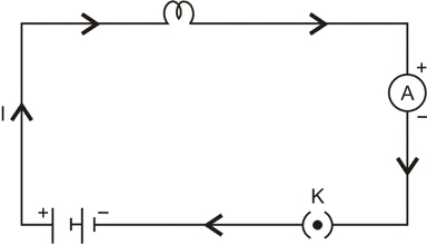
Figure showing direction of flow of conventional current
HOW THE CURRENT FLOWS IN A WIRE :
As electric current is the flow of electrons in a metal wire (or conductor) when a cell or battery is connected across its ends. A metal wire has plenty of free electrons in it. When the metal wire has not been connected to a source of electricity like a cell or a battery, then the electrons present in it move at random in all the directions between the atoms of the metal wire as shown in figure.
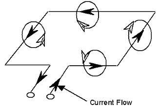
When a source of electricity like a cell or a battery is connected between the ends of the metal wire, then an electric force acts on the electrons present in the wire. Since the electrons are negatively charged, they start moving from negative end to the positive end of the wire and this flow of electrons constitutes the electric current in the wire.
HOW TO GET A CONTINUOUS FLOW OF ELECTRIC CURRENT:
It is due to the potential difference between two points that an electric current flows between them. The simplest way to maintain a potential difference between the two ends of a conductor so as to get a continuous flow of current is to connect the conductor between the terminals of a cell or a battery. Due to the chemical reactions going on inside the cell or battery, a potential difference is maintained between its terminals and this potential difference drives the current in a circuit.
ELECTRIC FIELD AND ELECTRIC POTENTIAL
The flow of electricity in a circuit can be regarded very much similar to the flow of water in a pipe. The water pipe is analogous to an electrical conductor, while the amount of water flowing through a given point per second corresponds to electric current.Figure below shows how the pump (P) builds up arid maintains pressure by lifting water from a tank (B) to the reservoir (A) through the pipe (R). Note that along the pipe, different points are at different pressure. Water in the pipe flows from, say, a point C to D only when the pressure at C is greater than that at D. Thus, when the value (V) is open, water would start flowing into the reservoir.
In the same manner electrons will move along a wire only if there is a difference of electric pressure called potential difference along the conductor. This difference of potential is produced by the cell or a battery, which acts like a water pump in the circuit.
The chemical action within the cell generates the difference in potential between the electrodes, which sets the electrons in motion and produces the current. We define the electric potential difference between the two points, A and B, on a conductor carrying current, as the work done to move a unit charge from A to B. Potential difference (V) between the points A and B = work done (W)/charge (Q). The unit of potential is volt, named after a scientist Alessandra (1745-1827).
One volt is the potential difference when 1 joule of work is done to move a charge of 1 C.
ELECTRIC FIELD:
Electric field due to a given charge is defined as the space around the charge in which electrostatic force of attraction or repulsion due to charge can be experienced by any other charge. If a test charge experiences no force at a point, the electric field at that point must be zero.
Electric field intensity at any point is the strength of electric field at that point. It is defined as the force experienced by a unit positive charge placed at that point.
If is the force acting on a test charge +q₀ at any point r, then electric field intensity at this point is given by
(r) = /q₀
Electric field is a vector quantity and its S.I. unit is Newton per coulomb or N/C.
ELECTRIC POTENTIAL:
The work done in charging a body is stored in it as its electric potential energy. The electric potential energy per unit charge is called electric potential.
Electric Potential = (Electric Potential Energy)/(Charge)
Mathematically,
V = W/q
Since work is measured in joule and charge in coulomb, therefore electric potential is measured in joule per coulomb (J/C). This unit occurs so often in our study of electricity, so it has been named as volt, in honour of the scientist Alessandra Volta (the inventor of the voltaic cell).
1 Volt = (1 joule)/(1 coulomb)
Potential is a scalar quantity, therefore it is added algebraically. For a positively charged body potential is positive and for a negatively charged body potential is negative.
ELECTRIC POTENTIAL DIFFERENCE:
Consider a charge Q placed at a point P. Let A and B be two other points (B being closer to A) as shown in figure.
● ○ ○
P A B
If a charge q is brought from infinity to A, a work W_A will be done.
The potential at A will then be, V_A = W_A/q
If charge q is brought from infinity to B, the work done will be W_B.
The potential at B will then be, V_B = W_B/q
The quantity V_B-V_A is called the potential difference between points A & B in the electric field of charge Q.
Mathematically we have, V_B - V_A = W_B/q - W_A/q
Electric potential difference is also measured in volt.
ELECTRIC CIRCUIT AND ITS COMPONENTS
All electrical appliances like lamps, heaters and air-conditioners, which work on electricity, are called Loads.
To pass electric current through any 'Load', it has to be connected to a source of electric power through wires called conductors.
A source of electric power (battery), loads and switches connected together through wires form an Electric Circuit.
There are many components or elements of an electric circuit:
Connecting wires: They are also called conductors.
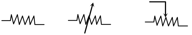
Resistors, Rheostats: It consists of wires made of Manganin and constantan alloys. Resistors provide fixed resistance whereas rheostats provide variable resistance.
Or
Resistor Rheostat
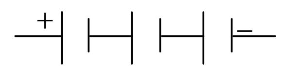
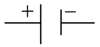
Battery: It is a combination of two or more cells.
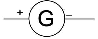
Galvanometer: It is a device used for detecting flow of current.
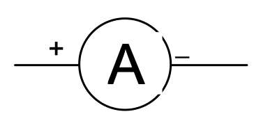
Ammeter: Also called as ampere-meter, it is used to measure current. It is always placed in series with the circuit.
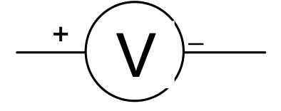
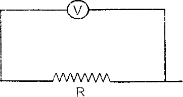
Voltmeter: Used for measuring potential difference. It is always connected in parallel across the circuit.
Closed electric circuit: In this, key is closed and current flows in the circuit continuously.
Open electric circuit: In this, key is open and no current flows in the circuit.
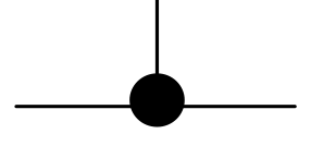
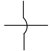
Wires crossing without joining
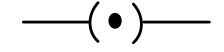
An electric cell
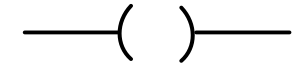
Electric bulb
OHM's LAW
The flow of electric current through a conductor depends on the potential difference across its ends. At a particular temperature, the strength of current flowing through it is directly proportional to the potential difference across its ends. This is known as Ohm's Law.
I ∝ V
or V ∝ IV = Potential difference
V = RIR = Resistance
or R = V/I I = Current
Here, R is the constant of proportionality, which depends on size, nature of material and temperature. R is called the electrical resistance or resistance of the conductor.
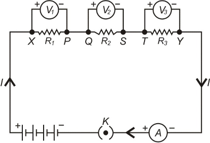
EXPERIMENTAL VERIFICATION OF OHM'S LAW
➢ Set up a circuit as shown in figure consisting of a nichrome wire XY of length, say 0.5 m, an ammeter, a voltmeter and four cells of 1.5 V each. (Nichrome is an alloy of nickel, chromium, manganese, and iron metal.)
➢ First use only one cell as the source in the circuit. Note the reading in the ammeter I, for the current and reading of the voltmeter V for the potential difference across the nichrome wire XY in the circuit. Tabulate them.
➢ Next connect two cells in the circuit and note the respective readings of the ammeter and voltmeter for the values of current through the nichrome wire and potential difference across the nichrome wire.
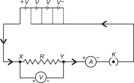
➢ Repeat the above steps using three cells and then four cells in the circuit separately.
➢ Calculate the ratio of V to I for each pair of potential difference (V) and current (I).
➢ Plot a graph between V and I, and observe the nature of the graph.
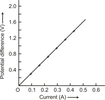
Thus, V/I is a constant ratio which is called resistance (R). It is known as Ohm’s Law.
RESISTANCE OF A CONDUCTOR:
The electric current is a flow of electrons through a conductor. When the electrons move from one part of the conductor to the other part, they collide with other electrons and with the atoms and ions present in the body of the conductor. Due to these collisions, there is some obstruction or opposition to the flow of electrons through the conductor.
The property of a conductor due to which it opposes the flow of current through it, is called resistance. The resistance of a conductor is numerically equal to the ratio of potential difference across its ends to the current flowing through it.
Resistance = (Potential difference)/(Current) Or R = V/I
UNIT OF RESISTANCE
The S.I. unit of resistance is Ohm (Ω)
1 Ohm (Ω) = (1 volt (1 V))/(1 Ampere (1 A))
The resistance of a conductor is said to be one ohm if a current of one ampere flows through it when a potential difference of one volt is applied across its ends.
CONDUCTORS, RESISTORS AND INSULATORS:
On the basis of their electrical resistance, all the substances can be divided into three groups:
conductors, resistors and insulators.
(i) Conductors: Those substances which have very low electrical resistance are called conductors. A conductor allows the electricity to flow through it easily. Silver metal is the best conductor of electricity Copper and Aluminium metals are also good conductors. Electric wires are made of Copper or Aluminium because they have very low electrical resistance.
(ii) Resistors: Those substances which have comparatively high electrical resistance, are called resistors. The alloys like nichrome, manganin and constantan (or ureka), all have quite high resistances, so they are used to make those electrical devices where high resistance is required. A resistor reduces the current in the circuit.
(iii) Insulators: Those substances which have infinitely high electrical resistance are called insulators. An insulator does not allow electricity to flow through it. Rubber is an excellent insulator. Electricians wear rubber handgloves while working with electricity because rubber is an insulator and protects them from electric shocks. Wood is also a good insulator.
CAUSE OF RESISTANCE:
There are many free electrons in a conductor. They move randomly when no electric current is passing through it. But when current is passed through it, they being negatively charged, start moving towards positive end of conductor, with a velocity called Drift velocity. During this movement, they collide with atoms, or ions of the conductor and thus their velocity is slowed down. This slow down due to obstruction is called Resistance.
Activity to show that the amount of current through an electric component depends upon its resistance:
➢ Take a nichrome wire, a torch bulb, a 10 W bulb and an ammeter (0-5 A range), a plug key and some connecting wires.
➢ Set up the circuit by connecting four dry cells of 1.5 V each in series with the ammeter leaving a gap XY in the circuit, as shown in figure.
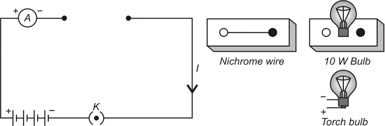
➢ Complete the circuit by connecting the nichrome wire in the gap XY. Plug the key. Note down the ammeter reading. Take out the key from the plug. [Note: Always take out the key from the plug after measuring the current through the circuit.]
➢ Replace the nichrome wire with the torch bulb in the circuit and find the current through it by measuring the reading of the ammeter.
➢ Now repeat the above step with 10 W bulb in the gap XY.
➢ You will notice that the ammeter readings differ for different components connected in the gap XY.
➢ You may repeat this Activity by keeping any material component in the gap. Observe the ammeter readings in each case. Analyse the observations.
Thus, we come to a conclusion that current through an electric component depends upon its resistance.
FACTORS AFFECTING RESISTANCE OF A CONDUCTOR
Resistance depends upon the following factors:-
(i) Length of the conductor.
(ii) Area of cross-section of the conductor (or thickness of the conductor).
(iii) Nature of the material of the conductor.
(iv) Temperature of the conductor.
Mathematically: It has been found by experiments that:
(i) The resistance of a given conductor is directly proportional to its length i.e.
R ∝ l ....(i)
(ii) The resistance of a given conductor is inversely proportional to its area of cross-section i.e.
R ∝ 1/A ....(ii)
From (i) and (ii), R ∝ l/A
R = ρ×l/A ...(iii)
Where ρ (rho) is a constant known as resistivity of the material of the conductor. Resistivity is also known as specific resistance.
DEPENDANCY OF RESISTANCE ON TEMPERATURE:
If R₀ is the resistance of the conductor at 0°C and R₁ is the resistance of the conductor at t°C then the relation between R₀ and R₁ is given by,
R₁ = R₀ (1 + θα∆t) [Here ∆t = t - 0 = t]
Or α = (R₁ - R₀)/(R₀t)
Here, α = Coefficient of Resistivity, t = temperature in °C
Experiment to show that resistance of a conductor depends on its length, cross section area and nature of its material.
Procedure:
➢ Complete an electric circuit consisting of a cell, an ammeter, a nichrome wire of length ℓ [marked (1)] and a plug key, as shown in figure.
➢ Now, plug the key. Note the current in the ammeter.
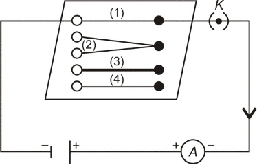
➢ Replace the nichrome wire by another nichrome wire of same thickness but twice the length, that is 2ℓ [marked (2)].
➢ Note the ammeter reading.
➢ Now replace the wire by a thicker nichrome wire, of the same length ℓ [marked (3)]. A thicker wire has a larger cross-sectional area.
➢ Again note down the current through the circuit.
➢ Instead of taking a nichrome wire, connect a copper wire [marked (4)] in the circuit. Let the wire be of the same length and same area of cross-section as that of the first nichrome wire [marked (1)].
➢ Note the value of the current.
➢ Notice the difference in the current in all cases.
➢ We notice that the current depends on the length of the conductor.
➢ We also observed that the current depends on the area of cross-section of the wire used.
RESISTIVITY:
Resistivity, ρ = (R × A)/l ....(iv)
By using this formula, we will now obtain the definition of resistivity. Let us take a conductor having a unit area of cross-section of 1 m² and a unit length of 1 m. So, putting A= 1 and l = 1 in equation (iv),
we get:
Resistivity, ρ = R
The resistivity of a substance is numerically equal to the resistance of a rod of that substance which is 1 metre long and 1 metre square in cross-section.
Unit of resistivity,
'ρ' = (ohm × (metre)²)/metre = ohm – metre
The S.I. unit of resistivity is ohm-metre which is written in symbols as Ω - m.
Resistivity of a substance does not depend on its length or thickness. It depends only on the nature of the substance. The resistivity of a substance is its characteristic property. So, we can use the resistivity values to compare the resistances of two or more substances.
(i) Importance of resistivity:
A good conductor of electricity should have a low resistivity and a poor conductor of electricity should have a high resistivity. The resistivities of alloys are much more higher than those of the pure metals. It is due to their high resistivities that manganin and constantan alloys are used to make resistance wires used in electronic appliances to reduce the current in an electrical circuit.
Nichrome alloy is used for making the heating elements of electrical appliances like electric irons, room-heaters, water-heaters and toasters etc. because it has very high resistivity and it does not undergo oxidation (or burn) even when red-hot.
(ii) Effect of temperature on resistivity:
The resistivity of conductors (like metals) is very low. The resistivity of most of the metals increases with temperature. On the other hand, the resistivity of insulators like ebonite, glass and diamond is very high and does not changes with temperature. The resistivity of semi-conductors like silicon and germanium is in between those of conductors and insulators and decreases on increasing the temperature. Semi-conductors are proving to be of great practical importance because of their marked change in conducting properties with temperature and impurity concentration.
SPECIFIC USE OF SOME CONDUCTING MATERIALS:
Tungsten: It has high melting point of 3380ºC and emits light at 2127ºC. It is thus used as a filament in bulbs.
Nichrome: It has high resistivity and melting point. It is used as an element in heating devices.
Constantan and Manganin: They have modulated resistivity. Thus they are used for making resistances and rheostats.
Tin-lead Alloy: It has low resistivity and melting point. Thus it is used as fuse wire.
COMBINATION OF RESISTORS
Many times we have to join two or more resistances to get the desirable resistance. There are two ways in which resistances be joined:
(a) Resistances in series
(b) Resistances in Parallel
RESISTANCES IN SERIES
A number of resistances are said to be connected in series if they are joined end to end and the same current flows through each one of them, when a potential difference is applied across the combination.
R₁, R₂, R₃ — Resistances in series.
V — Total potential difference across XY.
V₁, V₂, V₃ — Potential difference across R₁, R₂, R₃ respectively.
I — Current flowing through combination.
So, V = V₁ + V₂ + V₃ ... (i) [Potential difference gets divided among resistances joined in series]
According to Ohm's Law:
V₁ = IR₁ ... (ii)
V₂ = IR₂ ... (iii)
V₃ = IR₃ ... (iv)
Let R is the resultant or equivalent resistance of the combination. Then
V = IR ... (v)
From (i), (ii), (iii), (iv) and (v) we get that:
IR = IR₁ + IR₂ + IR₃
IR = I(R₁ + R₂ + R₃)
∴ R = R₁ + R₂ + R₃
THINGS TO REMEMBER IN SERIES CONNECTION:
(a) When a number of resistances are connected in series, the equivalent or resultant resistance is equal to the sum of individual resistances and resultant resistance is greater than any individual resistance.
(b) If n resistances each of value R are connected in series, the equivalent resistance R_e is given by:
R_e = R + R + R ........... n times
R_e = nR
R_e = Number of resistors × resistance of each resistor
(c) Equal current flows through each resistance and it is also equal to the total current in the circuit. This is because there is no other path along which the current can flow.
(d) The potential difference across the ends of the combination is distributed across the ends of each of the resistances. The potential difference across any one of the resistances is directly proportional to its resistance.
(e) The equivalent resistance when used in place of the combination of resistances produces the same current with the same potential difference applied across its ends.
(f) When two or more resistances are joined in series, the result is the same as increasing the length of the conductor. In both cases the resultant resistance is higher.
(g) In a series combination, the equivalent resistance is greater than the greatest resistance in the combination.
RESISTANCES IN PARALLEL:
A number of resistors are said to be in a parallel connection if one end of each resistance is connected to one point and the other is connected to another point. The potential difference across each resistor is the same and is equal to the applied potential difference between the two points.
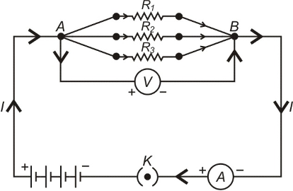
Resistances in Parallel Connection
R₁, R₂, R₃ — Three resistances in parallel connection.
V — Potential difference across A and B.
I — Total current flowing between A and B.
I₁, I₂, I₃ — Current flowing through R₁, R₂, R₃ respectively.
I = I₁ + I₂ + I₃ ... (i)
[In parallel connection, the current gets divided among the resistances]
The potential difference across R₁, R₂ and R₃ is same, therefore, according to Ohm's law:
I₁ = V/R₁ ⎫
I₂ = V/R₂ ⎬ ... (ii)
I₃ = V/R₃ ⎭
Let Rₑ be the equivalent resistance. Thus
I = V/Rₑ ... (iii)
From equation (i), (ii) and (iii) we get
V/Rₑ = V/R₁ + V/R₂ + V/R₃
V/Rₑ = V[1/R₁ + 1/R₂ + 1/R₃]
1/Rₑ = 1/R₁ + 1/R₂ + 1/R₃
THINGS TO REMEMBER IN PARALLEL CONNECTION:
(a) When a number of resistances are connected in parallel, the reciprocal of the equivalent or resultant resistance is equal to the sum of reciprocals of the individual resistances and is always smaller than the individual resistances. This is because there are a number of paths for the flow of electrons.
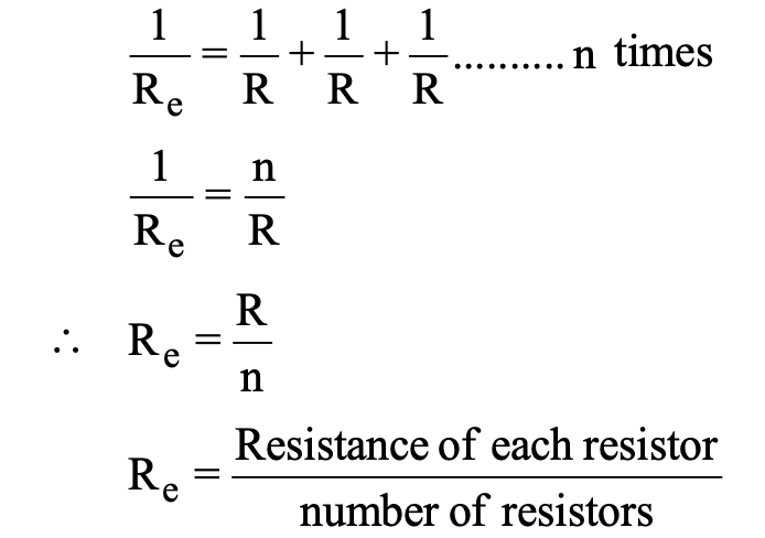
(b) If there are n resistances connected in parallel and each resistance has a value of R
(c) The potential difference across each resistance is the same and is equal to the total potential difference across the combination.
(d) The total current divides itself and different current flows through each resistor. The maximum current flows through the resistor having minimum resistance and vice versa.
(e) If an equivalent resistance ReR_e Re is connected in place of combination, it produces the same current for the same potential difference applied across its ends.
(f) In a parallel combination, the equivalent resistance is lesser than the least of all the resistances.
(g) If two resistances R1 and R2 are connected in parallel then
(h) If there are n resistors each of resistance R – Let RS be the resultant resistance of series combination and Rp be the resultant resistance of parallel combination.
Then, RS = nR
Rp = R/n
∴ Rs/Rp = nR/R/n = n2
HEATING EFFECT OF ELECTRIC CURRENT:
When the ends of a conductor are connected to a battery, then free electrons move with drift velocity and electric current flows through the wire. These electrons collide continuously with the positive ions of the wire and thus the energy taken from the battery is dissipated. To maintain the electric current in the wire, energy is taken continuously from the battery. This energy is transferred to the ions of the wire by the electrons. This increases the thermal motion of the ions, as a result the temperature of the wire rises. The effect of electric current due to which heat is produced in a wire when current is passed through it is called heating effect of current or Joule heating. In 1841 Joule found that when current is passed through a conductor the heat produced across it is:
(i) Directly proportional to the square of the current through the conductor i.e. H ∝ I2
(ii) Directly proportional to the resistance of the conductor i.e. H∝ R
(iii) Directly proportional to the time for which the current is passed i.e. H∝ t
Combining the above three equations we have H∝ I2 Rt
Where J is called Joule's mechanical equivalent of heat and has a value of J = 4.18 J cal-1. The above equation is called Joule's law of heating.
In some cases, heating is desirable, while in many cases, such as electric motors, generators or transformers, it is highly undesirable. Some of the devices in which heating effect of an electric current is desirable, are incandescent lamps, toasters, electric irons and stoves. The tungsten filament of an incandescent lamp operates at a temperature of 2700°C. Here, we see electrical energy being converted into both heat and light energy.
ELECTRIC ENERGY
To maintain an electric current to pass through the conductor, a continuous work has to be done. The total work done by a current in an electric circuit is known as Electric Energy.
DERIVATION OF WORK DONE AND ELECTRIC ENERGY
Now we know that:
Current (I) = charge (Q)/time (t) or Q = IT ... (i)
Also, potential difference is the work done in bringing a charge Q from one end to the other end of the conductor. Thus
(Potential Difference) V = W/Q
W = VQ ... (ii)
From (i) and (ii), we get that
W = V(It)
W = VIT ... (iii)
But according to Ohm's law
V = IR ... (iv)
From equation (iii) and (iv), we get that
W = (IR)(IT)
W = I²Rt
But I = V/R and by putting this value in equation (iii), we get
W = V.(V/R).t
W = V²t/R
This work done (W) by the current, measures the Electric Energy. Thus
W ∝ I² W ∝ R W ∝ t
Thus, W = H = VIt = I²Rt = V²t/R
(i) Commercial unit of electrical energy (Kilowatt - hour):
The S.I. unit of electrical energy is Joule and we know that for commercial purposes we use a bigger unit of electrical energy which is called "Kilowatt - hour". One Kilowatt - hour is the amount of electri-cal energy consumed when an electrical appliance having a power rating of 1 Kilowatt and is used for 1 Hour.
(ii) Relation between Kilowatt hour and Joule:
Kilowatt-hour is the energy supplied by a rate of working of 1000 watts for 1 hour.
1 kilowatt-hour= 3600000 joules
⇒ 1kWh=3.6 × 10⁶J
ELECTRIC POWER:
The rate at which electric energy is dissipated or consumed, is termed as electric power. The power P is given by, P = W/t = I2 R
The unit of electric power is watt, which is the power consumed when 1 A of current flows at a potential difference of 1V.
(i) Unit of power:
The S.i. unit of electric power is ‘watt' which is denoted by the letter W. The power of 1 watt is a rate of working of 1 joule per second.
A bigger unit of electric power is kilowatt.
1 kilowatt (kW) = 1000 watt.
Power of an agent is also expressed in horse power (hp).
1 hp = 746 watt.
(ii) Formula for calculating electric power:
We know, Power, P = Work/time
And Work, W = V × I × t Joules
P = (V × I × t)/t
∴ P = V × I
P = V × I
Power P in terms of I and R: Now from Ohm's law we have, V/I = R
V = I × R
P = I × R × I
P = I² × R
Power P in terms of V and R: We know, P = V × I
From Ohm's law I = V/R
P = V × V/R
P = V²/R
Power - Voltage Rating of Electrical Appliances:
Every electrical appliance like an electric bulb, radio or fan has a label or engraved plate on it which tells us the voltage (to be applied) and the electrical power consumed by it. For example, if we look at a particular bulb in our home, it may have the figures 220V, 100W written on it. Now, 220V means that this bulb is to be used on a voltage of 220 volts and 100W which means it has a power consumption of 100 watts or 100 joules per second.
ELECTRIC FUSE:
An electric fuse is an easily fusible wire of short length put into an electrical circuit for protection purposes. It is arranged to melt ("blow") at a definite current. It is an alloy of lead and tin (37% lead + 63% tin). It has a low resistivity and low melting point. As soon as the safe limit of current exceeds, the fuse "blows" and the electric circuit is cut off.
Consider a wire of length L, radius r and resistivity ρ. Let I be the current flowing through the wire. Now rate at which heat is produced in the wire is,
P= I2 R = I2 ρL/πr2 [∴ ρL/A =ρL/πr2]
This heat increases the temperature of the wire. Due to radiation some heat is lost. The temperature of the fuse becomes constant when the heat lost due to the radiation becomes equal to the heat produced due to the passage of current. This gives the value of current which can safely pass through the fuse.
In other words we have, I ∝ r3/2
HOUSE-HOLD ELECTRICAL CIRCUIT:
Electric power is usually generated at places which are very far from the places where it is consumed. At the generating station, the electric power is generated at 11,000 volt (because voltage higher than this causes insulation difficulties, while the voltage lower than this involves high current). This voltage is alternating of frequency 50 Hz (i.e. changing its polarity 50 times in a second). The power is transmitted over long distances at high voltage to minimise the loss of energy in the transmission line wires. For a given electric power, the current becomes low at a high voltage and therefore the loss of energy due to heating (=I2 Rt) becomes less. Thus, the alternating voltage is stepped up from 11 kV to 132 kV at the generating station (or called grid sub-station). It is then transmitted to the main sub-station. At the main sub-station, this voltage is stepped down to 33 kV and is transmitted to the switching transformer station or the city sub-station. At the city sub-station, it is further stepped down to 220 V for supply to the consumer as shown in figure.
To supply power to a house either the overhead wires on poles are used or an underground cable is used. Before the electric line is connected to the meter in a house, a fuse of high rating (» 50 A) is connected at the pole or before the meter. This is called the company fuse. The cable used for connection has three wires: (i) live (or phase) wire, (ii) neutral wire and (iii) earth wire. The neutral and the earth wires are connected together at the local sub-station, so the neutral wire is at the earth potential. After the company fuse, the cable is connected to a kWh meter. From the meter, connections are made to the distribution board through a main fuse and a main switch.
The main switch is a double pole switch. It has iron covering. The covering is earthed. This switch is used to cut the connections of the live as well as the neutral wires simultaneously. The main switch and the meter are locally earthed (in the compound of house). From the distribution board, the wires go to the different parts of the house.
There are two systems of wiring which are in common use:
(i) the tree system
(ii) the ring system
(a) Tree System:
In this system, different branch lines are taken from the distribution board for the different parts of the house. These branch lines look like the different branches of a tree. Each branch line is taken to a room through a fuse in the live wire. The different circuits are connected in parallel so that if there is a short circuiting in one distribution circuit, its fuse will blow off, without affecting the electric supply in the other circuits. The neutral N and the earth E are common for all circuits. The connection to the neutral N is to complete the circuit. All the appliances in a room are connected in parallel so that they work at the same voltage. The line wires used for connections should be of proper current carrying capacity depending on the rating of the appliance to avoid their overheating. The overheating in line often results in fire. The switches and sockets should also have the proper current carrying capacity.
Disadvantage:
(i) It requires plugs and sockets of different sizes for different current carrying capacities.
(ii) When the fuse in one distribution line blows, it disconnetcts all the appliances in the distributin line.
(iii) This wiring is expensive.
(iv) If a new appliance is to be installed requiring higher current, say 15A, while the original circuit in the room is for 5A rating, then it is necessary to put new leads upto the distribution box. This could be quite expensive and inconvenient.
(b) Ring System:
The ring-system of electric wiring is now rapidly replacing the older tree system described above. It consists of a ring-circuit. Wires starting from the main fuse-box, run around all the main rooms of the house and then come back to the fuse-box again. The fuse box contains a fuse of rating about 30 A. A separate connection is taken from the live wire of the ring for each appliance. The terminal of the appliance is connected to the live wire through a separate fuse and a switch. If the fuse of one appliance burns, it does not affect the other apliances. For each appliance, the wires used for connection should be of proper current carrying capacity.
Advantages:
It can be noted that the current can travel to an individual appliance through two separate paths. Thus effectively the connection for each appliance is through double thickness of wire. Therefore the wire used for ring main is of a lower rating than that which would be required for a direct connection to the mains. This reduces the cost of wiring considerably. Plugs and sockets of the same size can be used, but each plug should have its own fuse of rating suitable for the particular appliance.
Another advantage of this system is in installing a new appliance, since a new line up to the distribution box is not required. The appliance can be directly connected to ring main in the room. The only consideration is that the total load on the ring circuit should not exceed the main fuse viz. 30 A.
(c) Domestic Heating Applications:
Electric appliances like iron, heater, radiator etc. depend on the fact that when a current is sent through a wire, the wire is heated up and it begins to radiate energy.
The most widely used material for making the heater wire is nichrome. It is an alloy of nickel and chromium in the ratio of 4 : 1. It is chosen because of the following reasons :
(i) It has high resistivity. A nichrome wire of ordinary length shows sufficient resistance.
(ii) It can withstand high temperature without oxidation.
(iii) Its melting point is very high.
(d) Hazards of Electricity :
We have seen earlier that touching a bare electricity wire with current flowing through it can give a dangerous electric shock. This is because electricity then flows through the body and damages the cells. The amount of damage caused depends on the magnitude of current and the duration for which it flows in the body. The magnitude of current increases if the body is wet. That is why we are always advised not to touch any electrical appliances or a switch with wet hands.
A severe electric shock affects the muscles. Sometimes the shock may be so severe that the person may not be able to use his muscle to pull his hand away from the wire. In extreme cases, the heart muscles may get affected and may even lead to death.
EARTHING
Earthing means to connect the metal case of electrical appliance to the earth (at zero potential) by means of a metal wire called "earth wire". In household circuits, we have three wires, the live wire, the neutral wire and the earth wire. One end of the earth wire is buried in the earth. We connect the earth wire to the metal case of the electrical appliance by using a three-pinplug. The metal casing of the appliance will now always remain at the zero potential of the earth. We say that the appliance has been earthed or grounded.
If, by chance, the live wire touches the metal case of the electric iron (or any other appliance) which has been earthed, then the current passes directly to the earth through the earth wire. It does not need our body to pass the current and therefore, we do not get an electric shock. Actually, a very heavy current flows through the earth wire and the fuse of houshold wiring blows out or melts. And it cuts off the power supply. In this way, earthing aiso saves the electrical appliance from damage due to excessive current.
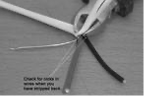
COLOUR CODING OF WIRES:
An electric appliance is provided with a three-core flexible cable. The insulation on the three wires is of different colours. The old convention is red for live, black for neutral and green for earth. The new international convention is brown for live, light blue for neutral and green (or yellow) for earth.
GALVANOMETER:
A galvanometer is an instrument that can detect the presence of current in a circuit. The pointer remains at zero (the centre of the scale) for zero current flowing through it. It can deflect either to the left or to the right of the zero mark depending on the direction of current.
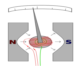
Galvanometers are of two types
(i) Moving coil galvanometer
(ii) Moving magnet galvanometer
It is used to make ammeter and voltmeter as follows :
(a) Ammeter:
Ammeter is an electrical instrument which measures the strength of current in 'ampere' in a circuit which is always connected in series in circuit so that total current (to be measured) may pass through it. The resistance of an ideal ammeter is zero (practically it should be minimum).
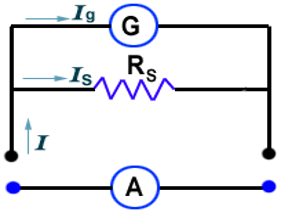
Conversion of Galvanometer into Ammeter
(b) Voltmeter:
It is an electrical instrument which measures the potential difference in 'volt' between two points of electric circuit. The only difference between ammeter and voltmeter is that ammeter has a negligible (approximately zero) resistance so that it may measure current of circuit passing through it more accurately giving the deflection accordingly, while the voltmeter passes negligible current through itself so that potential difference developed due to maximum current passing through circuit may be measured.
Voltmeter has a very high resistance and the resistance of an ideal voltmeter is infinite. A voltmeter is always connected in parallel.
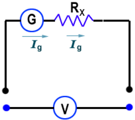
Conversion of Galvanometer into Voltmeter.
Ex.: What does an electric circuit mean?
Sol. An electric circuit is a continuous and closed path of an electric current. If the electric circuit is complete, electric current can flow through the circuit. If the circuit is broken anywhere or switched-off, the circuit is turned off, the current stops flowing.
Ex.: Define the unit of current.
Sol. SI unit of electric current is 1 ampere. Rate of flow of 1 coulomb of charge per second across a cross-section of a conductor constitutes 1 ampere current.