Thevenin’s Theorem Explanation
Thevenin's theorem is a powerful concept in electrical engineering that simplifies the analysis of complex linear circuits. It states that any complex network of resistors, voltage sources, and current sources can be reduced to a single equivalent circuit. This equivalent circuit consists of a single voltage source Vs and a series resistor Rs.
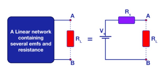
In the Thevenin equivalent circuit, the original circuit's resistive elements are consolidated into a single equivalent resistance Rs. Similarly, multiple independent voltage sources are replaced by a single equivalent voltage source Vs.
Thevenin’s Theorem Example
Thevenin’s Theorem can be understood with the help of the following example
Example:
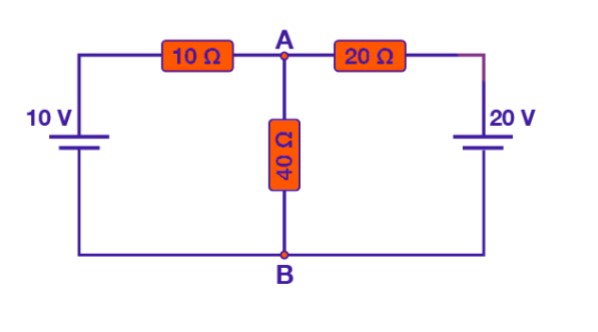
- Step 1: Begin by removing the load resistor Rload, such as 40 ohms in this example, to simplify the circuit.
- Step 2: To eliminate the effect of internal resistance in voltage sources within a circuit, short-circuiting all voltage sources is essential (setting v=0). If there are any current sources present, they should be open-circuited to similarly remove their internal resistance. This procedure is crucial for establishing ideal voltage or current sources, optimizing the circuit for accurate analysis and solution.
- Step 3: To find the equivalent resistance of a circuit, you start by removing the load resistance and identifying the voltage sources.
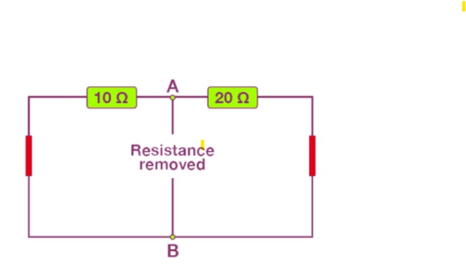
- In a given example, resistors like 10 Ω and 20 Ω are connected in parallel with a 20 Ω resistor.
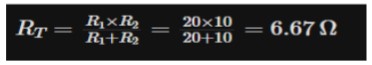
- By applying the parallel resistor formula, the equivalent resistance of the circuit is calculated to be 6.67 ohms."
- Step 4: Find the equivalent voltage.
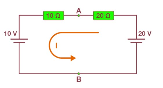
- To find the equivalent voltage, reconnect the voltage sources within the circuit. Calculate the current circulating through the loop using the equation: "as the voltage between Vs = VAB."
.jpg)
Since both resistors carry identical currents, we can calculate the voltage drop across them using either of these formulas:
- For the 20-ohm resistor: \( V_{AB} = 20V - (20 \Omega \times 0.33A) = 13.33V \)
- For the 10-ohm resistor: \( V_{AB} = 10V + (10 \Omega \times 0.33A) = 13.33V \)
This means both resistors experience the same voltage drop across them.
- Step 5: Construct the Thevenin equivalent circuit, which comprises a single voltage source Vs (e.g., 13.33 V) and a series resistor Rs (e.g., 6.67 ohms).
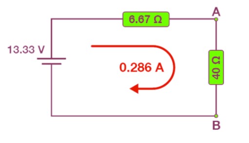
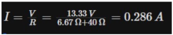
We can calculate the current in the circuit as:
Application of Thevenin’s Theorem
Thevenin’s theorem is widely applicable in both AC and DC circuits, particularly those containing linear components such as resistors, inductors, and capacitors. By replacing a complex circuit with a simpler equivalent, it facilitates easier analysis and design, making it a fundamental tool in electrical engineering.