The Light chapter in Class 9 Science explains reflection, refraction, lenses, and the nature of light. Using NCERT solutions for Class 9 Science, students can solve problems on image formation, mirrors, and lenses accurately. Our class 9 notes summarize laws of reflection, refraction, and optical phenomena like dispersion and total internal reflection. Class 9 science tuition helps students visualize light concepts through diagrams, ray tracing exercises, and practical experiments. Personalized Class 9 tuitions allow detailed doubt-solving and guidance in problem-solving techniques for optics. Learning light concepts not only helps in scoring well in exams but also enhances understanding of everyday optical devices like cameras, glasses, and telescopes.
Light
Light is a form of energy. More specifically, light is a general term commonly used to refer to the "visible spectrum", which is the range of wavelengths (and their corresponding frequencies) that forms the visible part of the electro-magnetic spectrum. The ranges in wavelengths vary from 380 nm to 750 nm. Each wavelength corresponds to light of one particular colour so the "visible spectrum" range of wavelengths would look something like the block below if each wavelength appeared only once and they were all lined-up in order of increasing wavelength.
The term "visible spectrum" means the range of electro-magnetic energy that most people (i.e. those with "normal" vision) can see with the naked eye. This is just a small part of a much wider range of energies, many of which we cannot see but some of which are used in other ways, e.g. Radio Waves, Microwaves, Ultra Violet (UV) Light, Infra-Red (IR) Radiation, X-Rays, and other wavelengths such as those used in many different types of modern scanning equipment.
White Light
"White Light" is the way humans perceive and refer to our experience of receiving an approx. equal quantity of all the wavelengths (i.e. colours) in the visible spectrum. This explains why there are so many different "shades of white". That is, when we see "white" we are receiving all the colours in approximately equal amounts - but only approximately.
The combination of wavelengths (colours) received by our eyes usually contains a bit more of some than of others, hence some "whites" can appear to be slightly "yellow", some slightly "blue", and so on.
Black and Grey
Just as white is not a "spectral colour", neither is black or grey. White is the way we perceive an approx. equal presence of all colours and black is the absence of light/colour such that all colours/wavelengths are (equally) lacking.
Shades of grey also correspond to approximately the same amount of each colour, but in decreasing amounts along a scale from white (lots of "light" energy in the form of many different wavelengths, corresponding to different "colours", reaching the eye/brain) to black (no "light" energy, that is an imperceptibly small quantity of "light" energy in the form of many different wavelengths corresponding to different "colours" reaching the eye/brain).
Propagation of Light
Propagation: "Propagation" is a term used (in the context of light energy and also some other forms of energy, e.g. beams of X-rays, or sometimes other forms of energy that can be described as moving in "waves") to mean "movement". "Propagation" is mentioned to introduce this frequently-used term but initially it is sufficient to describe how light "travels", which means the same thing.
Light generally travels through the air in straight lines, only changing direction when it passes from one type of substance (called a "medium") to another. For example, light changes direction slightly when it moves from air into water, or from air into glass, or vice-versa. This change in the direction of travel of light is due to refraction, which is explained later.
Note: Note that there are some situations in which light travels in curves rather than straight lines - as explained by the physics of diffraction and interference, but for the simple cases of describing image formation within the eye and the manifestation and correction of short-sight and long-sight, it is sufficient to think of rays of light traveling through any one medium, such as air or water, in a series of straight lines.
How Light Reaches Objects
Light reaches objects from many different sources - both from large and powerful sources of illumination such as the sun or the main lights in a room, and also by reflection or scattering from all the surrounding objects.
What Happens When Light Reaches an Object
When light reaches an object it can do one, or some combination of, the following:
Absorption
Light energy goes into the object itself. Because the light goes into the object rather than leaving the surface of the object - and then some of that light entering the eye - the object is not "seen" as very bright. Instead, it is perceived to be dark (meaning that little light is traveling from that object into the eye).
However, the object might still be obvious to a viewer, e.g. a dull matt-black object would still be seen if observed on a clean white surface. In that case the contrast makes the presence of the dark object obvious.
Reflection
Light reaches the surface of a very shiny object and "bounces" off the object in the same way as a hard ball would bounce off an even flat surface (e.g. as in the game of snooker). That is, when it is reflected light leaves the surface of an object at a particular angle relative to the angle from which it reached that surface.
Scatter
On reaching the surface of an object, light leaves that surface not in any one particular direction, but in many directions spread over a wide range of angles. This applies particularly to non highly-polished surfaces, such as paper, or walls painted matt white. Scatter is the most common of these possibilities when visible light is incident on ordinary everyday solid/opaque objects.
This is another case of light entering the object instead of leaving the surface of the object.
Refraction
Refraction only applies to objects that light can pass through, such as blocks of glass or plastic, windows, water, and spectacles. It is mentioned here for completeness. In the context of explaining how light reaches a person's eye from objects in the real world in front of him/her, refraction is less important that the other possibilities described above. (However, note that refraction plays a very important role in the eye/visual system for other reasons, such as focusing images onto the retina - and is therefore explained on other pages later in this section.)
How We See Objects
Light that is either reflected from or scattered by a surface enables people to see that surface (object) because when light leaving the surface of the object enters the eye(s) and reaches the "screen" called the retina located at the back of the eye it causes signals to be transmitted to the brain. Those signals are then processed by the brain, generating the experiences we understand as seeing and our view of the world around us.
Because light is only reflected from a surface at the angle at which it arrived at that surface, reflections may only reach the eyes from a very limited range of angles. However, light scattered from surfaces travels in many more directions so is far more likely to reach and enter the eyes of people in the same area as the object. Most of our visual perception of the world around us is therefore due to scattered light. People only "see" (any object) when light from that object passes into at least one eye in such a way as to reach the back of the eye where signals corresponding to that light are sent to the brain and processed.
This occurs when some of the light propagating from objects around us reaches and enters our eyes - which dynamically adjust as necessary to produce (usually!) clear pictures called "images" of the objects we look at. These images are formed on a "screen" called the retina at the back of each eye.
Good eyesight/vision requires that the images formed on the retina are clear, sharp images.
Reflection of Light
When a ray of light falls on any surface, a part of the light is sent back to the same medium. This phenomenon where the incident light falling on a surface is sent back to the same medium is known as reflection.
Types of Reflection of Light
There are two types of reflection of light:
- Regular reflection
- Irregular reflection
Laws of Reflection of Light
If we know how light behaves when it is reflected we can use a mirror to change the direction in which the light is traveling. This happens when a mirror is placed at the entrance of a concealed drive to give warning of approaching traffic. An ordinary mirror is made by depositing a thin layer of silver on one side of a piece of glass and protecting it with paint. The silver - at the back of the glass - acts as the reflecting surface.
Regular Reflection
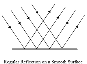
Regular reflection takes place when a ray of light is incident on a polished smooth surface like a mirror. Here the reflected ray of light moves only in a fixed direction.
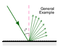
Irregular Reflection or Diffused Reflection
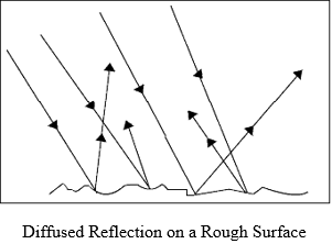
Irregular reflection or diffused reflection takes place when a ray of light is incident on a wall or wood, which is not smooth or polished. In this case, the different portions of the surface reflect the incident light in different directions. In such cases no definite image is formed, but the surface becomes visible. It is commonly known as scattering of light.
Thus diffused reflection makes non-luminous objects visible. Not all light, which hits an object, is reflected. Some of the incident light is absorbed. The brightness of an object depends on the intensity of the incident light and also on the reflectivity of the object.
Note: If a surface allows the entire incident light to undergo regular reflection then it will become invisible.
Reflection of Light by a Plane Surface
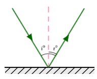
The figure shows how a ray of light is reflected by a plane surface. Let MM' represent a reflecting surface. When a ray of light is incident on MM' in the direction IO it gets reflected along the direction OR. IO is the incident ray; O is the point of incidence and OR is the reflected ray.
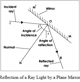
Let ON be the normal drawn perpendicular to the surface MM' at the point of incidence.
The angle which the incident ray makes with the normal at the point of incidence is called the angle of incidence and is denoted by the letter 'i'. The angle that the reflected ray makes with the normal at the point of incidence is called the angle of reflection 'r'. Mirror is an example of a reflecting surface.
The Laws of Reflection
The reflection at any plane surface is found to obey the laws of reflection. The laws of reflection are:
- The incident ray, the reflected ray and the normal at the point of incidence lie in the same plane.
- The angle of incidence is equal to the angle of reflection.
Image
An image can be real or virtual. A real image is formed when the rays of light actually intersect after reflection. A virtual image is formed when the light rays after reflection do not actually intersect but appear to diverge from it (these rays of light intersect when produced backwards).
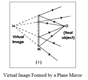
Formation of Image by a Plane Mirror - Ray Diagrams
The following rays are usually considered while constructing ray diagrams. A
A ray of light falling on a plane mirror at any angle gets reflected from the mirror such that the angle of incidence is equal to the angle of reflection.
Image Formation When an Object is placed between Two Inclined Mirrors
It has been found that if the mirrors are inclined at an angle θ then the number of images is given by the relation:
Number of images = 360°/θ - 1
If 360°/θ is not a whole number, then the number of images will be rounded off to the nearest integer. This can be verified by actual drawing.
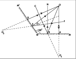
Case I: Mirrors Inclined at 120°
If the mirrors are inclined at 120° the number of images formed by the mirrors is given by the relation:
n = 360°/120° - 1 = 3 - 1 = 2
Let MM and MM' be two plane mirrors inclined at an angle 120° and O be the object placed in between these mirrors. In this case there will be only two images viz., O₁ and O₂.
Case II: Mirrors Inclined at 90°
Now let us consider the mirrors MM and MM' to be mutually perpendicular. In this case the number of images formed by the mirror is:
360°/90° - 1 = 4 - 1 = 3
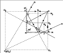
Steps for constructing the ray diagram:
- Place the mirrors MM' perpendicular to MM.
- An object O is kept in between these mirrors.
- OA and OB are the two rays, which are incident on the mirror MM.
- OA being normal to the surface retraces its path.
- OB makes an angle i with the normal N and gets reflected along BC according to the laws of reflection
- Extend the rays OA and BC backwards.
- They meet at O₁, which is the virtual image of O.
- OD and OE represent the rays which are incident on the mirror MM'.
- OD is perpendicular to the mirror MM' and hence gets reflected along the same path.
- OE is the incident ray and N₂ is the normal at the point of incidence and OE gets reflected along the path EF.
- Extend OD and EF backwards. They meet at O₂, which is the virtual image of O.
- The reflected ray BC gets internally reflected by the mirror MM' along CG.
- The ray DG appears to comes from O₃, which is the image of O₁.
- Similarly EF the reflected ray gets internally reflected by the mirror MM along FH.
- The ray FH appears to come from O₄, which is the image of O₂.
- The position of O₁ and O₂ coincide.
- Thus when the angle of inclination between the mirrors is 90° we get three images.
Case III: Parallel Mirrors (0° Inclination)
Let us now calculate the number of images formed if the two mirrors are placed parallel to each other i.e., the angle of inclination between them is 0°.
IMAGE
- Place the mirrors MM and MM' parallel to each other.
- An object O is kept between these mirrors.
- OA and OO' represent the rays which are incident on the mirror MM.
- OO' being normal retraces its path.
- OA makes an angle i with the normal N₁ and gets reflected along AB according to the laws of reflection.
- Extend the rays AB and OM backwards.
- They meet at I₁, which is the virtual image of the object O.
- The reflected ray AB gets reflected by the mirror MM' and forms an image I₂.
- Similarly I₃, I₄ etc. are formed.
- The light from I₁, I₂, I₃, I₄ etc. gets reflected and forms their images.
In this manner, many images are formed but the intensity of the remote images goes on decreasing due to absorption of light energy at every successive reflection and thus we see only finite number of images even though infinite images will be formed.
Uses of Plane Mirrors
A plane mirror is used:
- as a looking glass to view ourselves
- by interior designers to create an illusion of depth
- to fold light as in a periscope and other optical instruments
- to make kaleidoscope, an interesting toy
Spherical Mirrors for Reflection
A mirror whose polished, reflecting surface is a part of a hollow sphere of glass or plastic is called a spherical mirror. In a spherical mirror, one of the two curved surfaces is coated with a thin layer of silver followed by a coating of red lead oxide paint. Thus, one side of the spherical mirror is opaque and the other side is a highly polished reflecting surface. In a diagram the opaque side of a mirror is always shown shaded.
Note: In the diagrams given here, please remember that the opaque, non reflecting side is shaded grey. The reflecting side is black.
Types of Spherical Mirrors
Depending upon the nature of the reflecting surface of a mirror, the spherical mirror is classified as:
- Concave mirror
- Convex mirror
Concave Mirror
Concave mirror is a spherical mirror whose reflecting surface is towards the center of the sphere of which the mirror is a part.
Convex Mirror
Convex mirror is a spherical mirror whose reflecting surface is away from the center of the sphere of which the mirror is a part.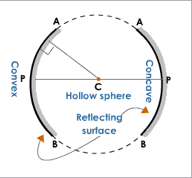
Physical Terms Related to Spherical Mirrors
Let us now define certain physical terms relating to spherical mirrors.
Center of Curvature
Center of Curvature is the center of the sphere of which the spherical mirror forms a part. It is denoted by the letter C.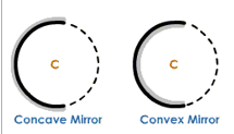
Radius of Curvature
Radius of Curvature is the radius of the sphere of which the mirror is a part. It is represented by the letter R.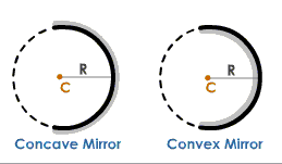
Linear Aperture
Linear aperture is the distance between the extreme points (X and Y) on the periphery of the mirror.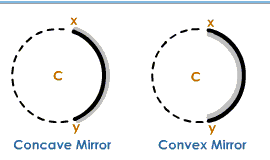
Pole
Pole is the midpoint of the aperture of the spherical mirror. It is represented by the letter P.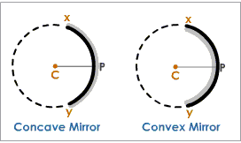
Principal Axis
Principal axis is the straight line passing through the pole and the center of curvature of a spherical mirror.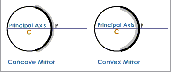
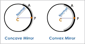
Normal
The normal at any point of the spherical mirror is the straight line obtained by joining that point with the center of the mirror. The normal at point A on the mirror is the line AC obtained by joining A to the center of curvature of the mirror. Normal at any point on a spherical mirror is equal to the radius of the sphere of which the mirror is a part.
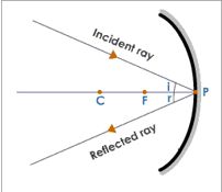
Principal Focus or Focus
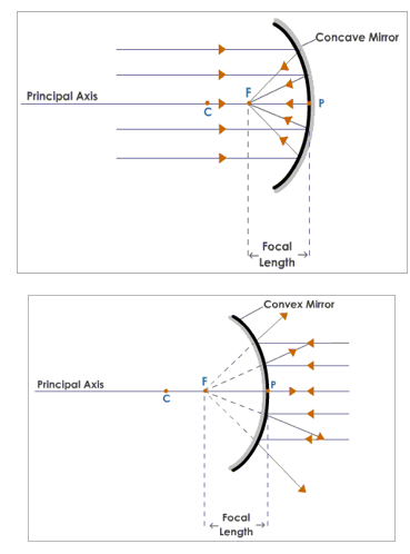
The rays of light parallel to the principal axis of a mirror after reflection, either pass through a point (in case of a concave mirror) or appear to diverge from a point (in the case of a convex mirror) on the principal axis and this point is referred to as the principal focus or focal point of the mirror. The principal focus of a spherical mirror may be defined as a point on its principal axis where a beam of light parallel to the principal axis converges to or appears to diverge from after reflection from the spherical mirror.
Focal Length
Focal length is the distance between the pole and the focus of a mirror. It is represented by the letter f.
Characteristics of Focus of a Concave and a Convex Mirror
| Convex Mirror | Concave Mirror |
|---|---|
| The focus lies behind the mirror | The focus is in front of the mirror |
| The focus is virtual as the rays of light after reflection appear to come from the focus | The focus is real as the rays of light after reflection converge at the focus |
Note: A concave mirror is also known as a converging mirror as the parallel rays of light after getting reflected from the concave mirror converge at the focus. A convex mirror is known as a diverging mirror as the parallel rays of light after reflection appear to come from a point, i.e., the rays diverge after reflection.
Formation of Images by Spherical Mirrors
When an object is placed in front of a concave mirror, light rays from the object fall on the mirror and get reflected. The reflected rays produce an image at a point where they intersect or appear to intersect. Formation of an image by mirrors is usually shown by constructing ray diagrams. To construct a ray diagram, we need at least two rays whose paths after reflection from the mirror are known. These rays must be chosen according to our convenience. Any two of the rays can be considered to obtain the image.
Standard Rays for Ray Diagrams
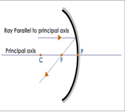
- A ray of light parallel to the principal axis after reflection from a concave mirror passes through its focus.
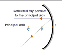
- A ray of light passing through the focus of a concave mirror after reflection emerges parallel to the principal axis.
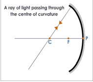
- A ray of light passing through the center of curvature of a concave mirror retraces its path after reflection as the ray passing through the center of curvature acts as a normal to the spherical mirror.
- A ray of light which strikes the mirror at its pole gets reflected according to the law of reflection.
Formation of Images by a Concave Mirror
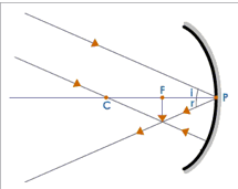
When Object is at Infinity
When an object is placed at infinity, the rays coming from it are parallel to each other. Let us consider two rays, one striking the mirror at its pole and the other passing through the center of curvature. The ray which is incident at the pole gets reflected according to the law of reflection and the second ray which passes through the center of curvature of the mirror retraces its path. These rays after reflection form an image at the focus. The image formed is real, inverted and diminished. The image is:
- at F
- Real
- Inverted
- Diminished
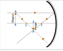
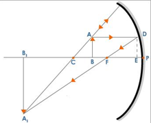
When the Object is Placed Beyond C
The two rays which are considered to obtain the image are:
- a ray passing through the center of curvature
- a ray parallel to the principal axis. The ray passing through the center of curvature retraces its path and the ray which is parallel to the principal axis passes through the focus after reflection. These rays after reflection meet at a point between C and F. The image is inverted, real and diminished.
The image is:
- Between C and F
- Real
- Inverted
- Diminished
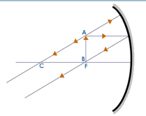
When the Object is Placed at the Center of Curvature
Here we consider the two rays, one parallel to the principal axis and the other passing through the focus. The ray of light which is parallel to the principal axis passes through the focus after reflection. The other ray passing through the focus after reflection emerges parallel to the axis. After reflection these rays meet at the center of curvature to form an inverted image, which is real and of the same size as the object. The image is:
- At C
- Real
- Inverted
- Same size as object
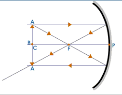
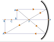
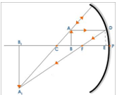
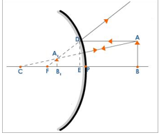
When the Object is Between C and F
Here we consider a ray of light which is parallel to the principal axis and another ray passing through the focus. The ray which is parallel to the principal axis passes through the principal focus and the ray which passes through the focus after reflection emerges parallel to the principal axis. The reflected rays meet at a point beyond C and the image is real, inverted and magnified. The image is:
- Beyond C
- Real
- Inverted
- Magnified
When the Object is at the Focus
Here, we consider a ray of light which is parallel to the principal axis and another ray passing through the center of curvature. The ray which is parallel to the principal axis passes through the focus and the ray which passes through the center of curvature retraces its path. The reflected rays are parallel to each other, and would meet only at infinity i.e., the image is formed at infinity and it is a real, inverted, enlarged image of the object. The image is:
- at infinity
- Real
- Inverted
- Magnified
When the Object is Between the Pole and the Focus
Here we consider a ray of light which is parallel to the incident ray and another ray which is passing through the center of curvature. The ray which is passing through the center of curvature retraces its path and the other ray which is parallel to the principal axis after reflection passes through the focus. These rays appear to meet behind the mirror when the reflected rays are extended backwards. The image is virtual, erect and magnified.
Summary Table for Concave Mirror
| Position of the object | Position of the image | Nature and size of the image | Use |
|---|---|---|---|
| At infinity | At the focus | Real, inverted and diminished | As collector of radiation in solar heating devices |
| Beyond the centre of curvature | Between the focus and the centre of curvature | Real, inverted and diminished | |
| At the centre of curvature | At centre of curvature | Real, inverted and same size as object | As a reflecting mirror behind a projector lamp |
| Between the focus and centre of curvature | Beyond the centre of curvature | Real, inverted and magnified | In flood lights |
| At focus | At infinity | Real, inverted and magnified | As a reflecting mirror in car, head lights, search lights etc. |
| Between the pole of the mirror and the focus | Appears behind the mirror | Virtual, erect and magnified | As a shaving mirror or makeup mirror and dentist's mirror |
Case II: Convex Mirror
The following rays are considered while constructing ray diagrams.
- A ray of light traveling parallel to the principal axis after reflection from a convex mirror appear to come from its focus behind the mirror.
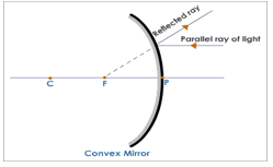
- A ray of light traveling towards the center of curvature behind the mirror hits the mirror at 90° and is reflected back along its path.
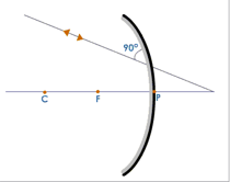
- A convex mirror always gives a virtual image irrespective of the position of the object.
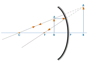
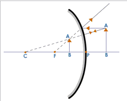
Formation of Image in a Convex Mirror
The image is:
- Formed between the pole and the focus
- Erect
- Diminished
- Virtual
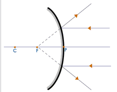
When the Object is at Infinity
The image is:
- Formed at the focus
- Extremely diminished
- Virtual
- Erect
Summary Table for Convex Mirror
| Position of the object | Position of the image | Size of the image | Nature of the image |
|---|---|---|---|
| At infinity | At focus | Extremely diminished | Virtual and erect |
| Between infinity and pole of the mirror | Between the focus and pole | Diminished | Virtual and erect |
Mirror Formula (Concave Mirror)
Mirror formula is the relationship between object distance (u), image distance (v) and focal length.
The mirror formula for a concave mirror is: 1/f = 1/v + 1/u
Sign Convention for Spherical Mirrors
The following sign convention is used for measuring various distances in the ray diagrams of spherical mirrors:
- All distances are measured from the pole of the mirror.
- Distances measured in the direction of the incident ray are positive and the distances measured in the direction opposite to that of the incident rays are negative.
- Distances measured above the principal axis are positive and that measured below the principal axis are negative.
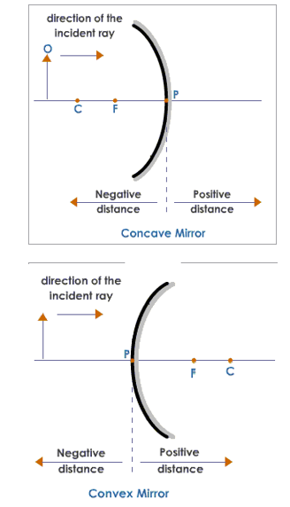
Table Showing the Sign Convention
| Type of mirror | u | v | f | R | h | 'h' of the image | |||
|---|---|---|---|---|---|---|---|---|---|
| Real | Virtual | Real | Virtual | Real | Virtual | ||||
| Concave mirror | - | - | + | - | - | + | - | + | |
| Convex mirror | - | No real image | + | + | + | + | No real image | + | |
Derivation of Mirror Formula
An object AB at a distance u from the pole of a concave mirror. The image A₁B₁ is formed at a distance v from the mirror. The position of the image is obtained by drawing a ray diagram. Consider the ΔA₁CB₁ and ΔACB ∠A₁CB₁ = ∠ACB (Vertically opposite angles) ∠AB₁C = ∠ABC (Right angles) ∠B₁A₁C = ∠BAC When two angles of ΔA₁CB₁ and ΔACB are equal then the third angle ∠B₁A₁C = ∠BAC ∴ ΔA₁CB₁ and ΔACB are similar
∴ AB/A₁B₁ = BC/B₁C
Similarly ΔFB₁A₁ and ΔFED are similar
∴ ED/A₁B₁ = FB/FB₁
But ED = AB
∴ AB/A₁B₁ = EF/FB₁
From equations (1) and (2):
∴ BC/B₁C = EF/FB₁
If D is very close to P then EF = PF
∴ BC/B₁C = PF/FB₁
BC = PC - PB B₁C = PB₁ - PC FB₁ = PB₁ - PF
(PC-PB)/(PB₁-PC) = PF/(PB₁-PF)
But PC=R, PB=u, PB₁ = v, PF = f By sign convention: PC = -R, PB = -u, PF = -f and PB₁ = -v ∴ Equation (3) can be written as: (-R-(-u))/(-v-(-R)) = (-f)/(-v-(-f)) (-R+u)/(-v+R) = (-f)/(-v+f) (u-R)/(R-v) = f/(v-f) uv - uf - Rv + Rf = Rf - vf uv - uf - Rv = Rf - Rf - vf uv - uf - Rv = -vf R = 2f uv - uf - 2fv = -vf uv - uf = 2fv - fv uv - uf = fv Dividing equation (4) throughout by uvf we get:
1/f - 1/v = 1/u
1/f = 1/v + 1/u
Equation (5) gives the mirror formula
Mirror Formula (Convex Mirror)
Let AB be an object placed on the principal axis of a convex mirror of focal length f. u is the distance between the object and the mirror and v is the distance between the image and the mirror.
In ΔABC and ΔA₁B₁C: ∠ABC = ∠A₁B₁C (Right angles) ∠ACB = ∠A₁CB₁ ∠CAB = ∠CA₁B (Common angle) ∴ ΔABC is similar to ΔA₁B₁C
∴ AB/A₁B₁ = BC/B₁C
Similarly ΔDEF is similar to ΔA₁B₁F
∴ DE/A₁B₁ = EF/B₁F
But DE = AB and when the aperture is very small EF = PF. ∴ Equation (2) becomes:
AB/A₁B₁ = PF/B₁F
∴ From equations (1) and (3) we get: PF/B₁F = BC/B₁C PF/(PF-PB₁) = (PB+PC)/(PC-PB₁) f/(f-v) = (-u+2f)/(2f-v) [PF = f, PB₁ = v, PB = u, PC = 2f] f(2f - v) = (f - v)(2f - u) 2f² - vf = 2f² - uf - 2fv + uv 2f² - vf - 2f² + uf + 2fv - uv = 0 uf + fv - uv = 0 Dividing both sides of the equation (4) by uvf we get: uf/uvf + fv/uvf - uv/uvf = 0
1/u + 1/v - 1/f = 0
1/u + 1/v = 1/f
Magnification
The ratio of the height of the image to the height of the object is called the linear magnification. It is denoted by the letter m.'
m = hI/hO
Where hI is the height of the image and hO is the height of the object We know that: m = hI/hO = AIBI/AB = FB₁/FE = (PB₁-PE)/PF m = (-v-(-f))/(-f) m = -(v-f)/f m = -v/f + f/f m = -(v/f) + 1 The mirror formula is 1/v + 1/u = 1/f m = hI/hO = -v(1/v - v/u) + 1 m = hI/hO = -1 - v/u + 1
Or m = hI/hO = -v/u
For a real image u and v are negative and the magnification is negative. Negative magnification means the image is inverted. On the other hand for a virtual image u is negative and v is positive and hence the magnification is positive, i.e., the image is erect.
Uses of Concave Mirror
The use of a concave mirror depends upon the distance of the object from the mirror. Some of the uses are listed below. Concave mirrors are used for the following purposes:
- as reflectors in the head lights of cars, search lights etc. to obtain parallel beam of light. For this, the source of light is placed at the focus of the concave reflector.
- by dentists to focus light on the tooth to be examined.
- as shaving mirrors and as make up mirrors to get an enlarged erect image of the face.
- to concentrate solar radiations in solar heating devices.
Uses of Convex Mirror
Convex mirrors are used for the following purposes:
- rear-view mirror in an automobile. This convex mirror gives the driver a clear view of the traffic approaching from behind.
- vigilance mirrors in departmental stores.