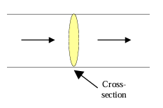
Flow of electric charge constitutes electric current. For a given conductor, if 'Q' charge flows through cross-section of area A in time 't', then the average electric current through the conductor is given as I = δQ/δt and its instantaneous value is dQ/dt
Mechanism of Current Flow in Metallic Conductor
Flow of current in metals is due to free electrons. In absence of any externally applied emf (by means of a battery) the free electrons move randomly through the metal from one point to another giving zero net current. When connected to a battery, the free electrons get accelerated due to the electric field (set up by the battery) and they gain velocity and energy.
However, the passage is not smooth and the electrons collide with the lattice ions in which the ultimate gainer (of energy) is the ion. As we know the temperature of a body is related with the energy of vibrations of these ions, these collisions results in increase in temperature of the metal.
The loss of energy of electrons in collision and their acceleration by the electric field, finally, results in drifting of electrons in a particular direction. (Although the actual motion of electrons is erratic, the overall effect is of drifting of electrons) If vd be the drift velocity and 'n' be the number of such free electrons per unit volume, the current through the conductor is I = neAvd (where, e = magnitude of electron's charge, A = c.s. area.)
- Current density: Current flowing per unit area through any cross section is called current density J = I/A. It is a vector quantity I = J·A
- Number density: Number of electrons per unit volume (n)
Example: A steady current passes through a cylindrical conductor. Is there an electric field inside the conductor?
Solution: Yes; No doubt under steady state conditions in electrostatics when conductor is charged electric field inside it is zero as metal is an equipotent surface. However when a potential difference is applied across a conductor and a steady current flows though it, condition no longer remains static and there exists an electric field inside the conductor given by E = ρJ.
OHM's Law
It states that "the potential difference across a conductor is directly proportional to the current flowing through it at a given temperature". At constant temperature: V/I = constant(R) the constant 'R' is called resistance of the conductor.
Note: Current density ∝ electric field. i.e. J⃗ = σE⃗ or J = σE, where, σ is a constant of proportionality called conductivity
Resistivity (ρ) and conductivity (σ)
The resistance R of a given conductor depends upon its length (ℓ) and cross-sectional area (A) such that R = ρℓ/A where ρ = resistivity of the material of the given conductor. Its S.I. unit is Ω.m. Reciprocal of resistivity is called the electrical conductivity (σ) of the material, thus σ = 1/ρ = ℓ/RA whereas reciprocal of resistance is called conductance of the given conductor. S.I. unit of conductivity σ is (Ω - m)⁻¹ and is usually written as mho/m.
Temperature Dependence of Resistivity
The conductivity of the material of a given conductor decreases as its temperature is increased. Thus resistivity increases with the rise in temperature. If ρT and ρ0 represent the resistivities at temperature T and T0 respectively, then for small temperature variations, ρT = ρ0 [1 + α(T - T0)] Where α is called the temperature coefficient of resistivity.
The resistivity varies over a very wide range. For metals (good conductor) ρ ≈ 10⁻⁸ Ω.m and for insulators ρ ≈ 10¹⁷ Ω.m Semiconductors (silicon, germanium) have intermediate value much smaller than insulator but much larger than metals. Temperature coefficient of resistivity is negative for semiconductors and positive for the metals. For superconductors resistivity is zero.
Also Read: Electrostatic Potential and Capacitance
Thermistor
A thermistor is a semiconductor electronic device in which the resistance decreases as its temperature increases. This is used as a thermometer, often forming one element in a resistance bridge. Thermistors are also used to compensate for the increased resistance of ordinary resistors when hot, also in vacuum gauges, time-delay switches and voltage regulators. The temperature coefficient of resistivity is negative for semiconductors, hence thermistors are usually prepared from oxides of various metals such as nickel, iron, cobalt and copper etc. A thermistor is used to detect small charges in temperature of the order of even 10⁻³ °C.
- For semiconductors: Their resistivity decreases exponentially with temperature.
- For Insulations: Their resistivity very high and doesn't vary appreciably with change in temperature
- For super conductors: Resistance of a conductor becomes zero at very low temperatures.
Kirchhoff's Law
Junction Rule (KCL):
It is based on the law of conservation of charge. At a junction in a circuit the incoming current is equal to the outgoing current. i.e., the algebraic sum of the currents at a junction is zero.
Loop rule (KVL)
It is based on the law of conservation of energy. The algebraic sum of the changes in potential around any closed path is zero.
- In case of a resistor of resistance 'R' potential will decrease in the direction of current. Hence, for the shown conductor: vb – va = -IR
- For an emf source, the potential changes will be obtained as illustrated below:
- Emf = ε, internal resistance = r: vb – va = ε - ir
- Emf = ε, internal resistance = r: vb – va = -ε - ir
Students can use any sign convention which they find easy.
Note: emf is defined on workdone in moving a unit charge once through a complete circuit.
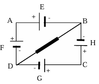
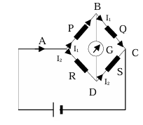
Example: In the series circuit shown, E,F,G,H are cells of emf 2V,1V,3V and 1V respectively, and their internal resistance are 2Ω, 1Ω, 3Ω and 1Ω respectively.
Calculate
(i) the potential difference between B and D and
(ii) the potential difference across the terminals of each of the cells G and H. [Circuit diagram with cells E, F, G, H arranged in series-parallel configuration]
Solution: Let us redraw the circuit. At junction D, we have applied the junction rule, whereby we get current in DE as shown.
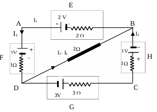
Loop BADB 2I₁ - 2 + 1 + I₁ + 2(I₁ - I₂) = 0 ∴ 5I₁ - 2I₂ = 1
Loop DCBD -3 + 3I₂ + I₂ + 1 - 2(I₁ - I₂) = 0 ∴ 6I₂ – 2I₁ = 2 ∴ I₁ = 5/13 A, I₂ = 6/13 A
(i) VBD = 2(I₁) - 2 + 1 + I₁ = 3I₁ - 1 = 3 × (5/13) - 1 = 2/13 V
(ii) Terminal voltage of G = |3 + 3.I₂| = |3 + 3 × (6/13)| = 21/13 V
Terminal voltage of H = |1 - I₂| = |1 - 6/13| = 19/13 V
Grouping of Resistances
Resistance in series
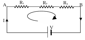
Let the equivalent resistance between A & B equals Req, by definition. Req = V/I ... (1)
Using Kirchoff's 2nd rule for the loop shown in figure, V = IR₁ + IR₂ + IR₃ ... (2)
From (1) and (2) Req = R₁ + R₂ + R₃
Resistance in parallel
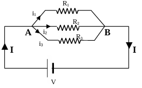
Here again, Req = V/I ... (1)
I = i₁ + i₂ + i₃ = V/R₁ + V/R₂ + V/R₃ ... (2)
From (1) and (2)
1/Req = 1/R₁ + 1/R₂ + 1/R₃
Example: Find the equivalent resistance between A and B in the circuit shown here. Every resistance shown here has a magnitude of 2Ω.
Solution: Points C, O & D are at the same potential. Therefore, resistances AO, AC and AD are in parallel.
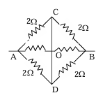
Similarly BC, BO and BD are in parallel.
∴ RAB = 1/3(2Ω) + 1/3(2Ω) = 4/3 Ω
= 1.33 Ω.
Energy, Power And Heating Effect
When a current I flows for time t from a source of emf E, then the amount of charge that flows in time t is Q = It. Electrical energy delivered W = Q.V = VIt Thus, Power given to the circuit, = W/t = VI or V²/R or I²R
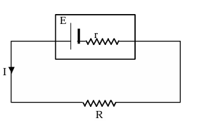
In the circuit
E.I = I²R + I²r, where EI is the rate at which chemical energy is converted to electrical energy, I²R is power supplied to the external resistance R and I²r is the power dissipated in the internal resistance of the battery.
An electrical current flowing through conductor produces heat in it. This is known as Joule's effect. The heat developed is given by H = I².R.t joule where I = current in ampere, R = resistance in Ω, t = time in second.
Maximum Power
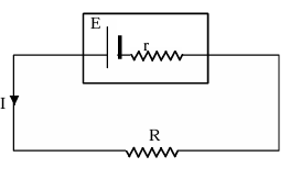
In a circuit, for what value of the external resistance the maximum power be drawn from a battery? For the shown network power developed in resistance R equals
P = E².R/(R + r)² (∵ I = E/(R + r) and P = I²R)
Now, for dP/dR = 0 (for P to be maximum dP/dR = 0) or
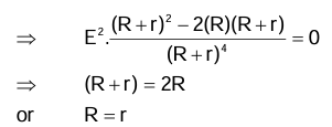
∴ The power output is maximum, when the external resistance equals the internal resistance. R = r
Example: A copper wire having a cross-sectional area of 0.5 mm² and a length of 0.1 m is initially at 25°C and is thermally insulated from the surroundings. If a current of 10 A is set up in this wire
(a) Find the time in which the wire starts melting. The change of resistance of the wire with temperature may be neglected.
(b) What will this time be, if the length of the wire is doubled? Density of Cu = 9 × 10³ Kg m⁻³ specific heat of Cu = 9 × 10⁻² Cal Kg⁻¹ °C⁻¹, M.P. (Cu) 1075 °C and specific resistance = 1.6 × 10⁻⁸Ωm.
Solution: (a) Mass of Cu = Volume × density = 0.5 × 10⁻⁶ × 0.1 × 9 × 10³= 45 × 10⁻⁵ Kg.
Rise in temperature = θ = 1075-25 = 1050 °C.
Specific heat = 9 × 10⁻² Kg⁻¹ °C × 4.2 J ∴ I²Rt = mSθ
t = mSθ/I².R
but R = ρL/A = 1.6 × 10⁻⁸ × 0.1/(0.5 × 10⁻⁶) = 3.2 × 10⁻³
t = (45 × 4.2 × 10⁻³ × 1050 × 0.09)/(10² × 3.2 × 10⁻³) = 558s
(b) When the length of wire is doubled, R is doubled, but correspondingly mass is also doubled. Therefore, wire will start melting in the same time.
Wheatstone Bridge
For a certain adjustment of Q, VBD = 0, then no current flows through the galvanometer.
VB = VD or VAB= VAD ⇒ I₁.P = I₂.R
Likewise, VBC = VDC ⇒ I₁.Q = I₂.S
Dividing, we get, P/Q = R/S
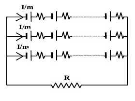
Grouping of Identical Cells
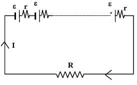
1. Series Grouping
E.m.f. of the cell is ε and internal resistance is r. R is the external resistance, I is the current through the circuit and n is the total number of cells. Applying Kirchhoff's law ε - ir + ε - ir + ........ (to n times ) - iR = 0
i = nε/(R + nr) Z
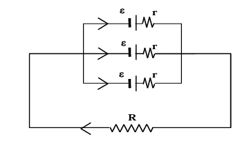
2. Parallel grouping
Applying Kirchhoff's law
ε - (I/n)r - IR = 0
I = nε/(r + nR)
3. Mixed grouping
Number of rows is m and number of cells in each row is n Applying kirchhoff's law nε - (I/m)r - IR = 0
I = mnε/(mR + nr)
For current through R to be maximum,
mR = nr
R = nr/m = total internal resistance
Example: Calculate the steady-state current in the 2Ω resistor shown. The internal resistance of the battery is negligible and the capacitance of the capacitor is 0.2μF.
Solution: The resistance of the parallel combination of 2Ω and 3Ω resistors is given by 1/R = 1/2 + 1/3 = 5/6
R = 1.2Ω
This resistance is in series with 2.8Ω giving a total effective resistance = 1.2 + 2.8Ω = 4Ω
In the steady state, charge on the capacitor C has stablised and hence no current passes through 4Ω resistor which is in series with the capacitor. Thus the current through the circuit = 6/4 = 1.5 A, VAB = 1.5 × 1.2 = 1.8 V, I through 2Ω resistor = 1.8/2 = 0.9 A.
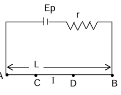
Potentiometer
It can measure P.D. without drowing a current from the circuit. Two it gives accurate reading and it can measure emf of a cell
AB = Potentiometer wise of resistance R and length L. any two points C and D are repeated by length l.
VCD = IRCD = (E_p/(r + R)) × (R/L) × l ... (1) ∴ VCD ∝ l (all other factors are constant)
The emf of a cell
A cell of emf E is balanced against length l of wire then, E = VCP = (Ep/(r + R)) × (R/L) × l
r₁(E₁/E₂) = (l₁/l₂)
Sensitivity of potentiometer: Small in the potential drop per unit length more in the sensitivity should be small. This can be achieved by increasing the length of potentiometer wire and decreasing the current through it.
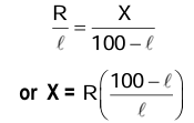
Meter bridge
Based on wheat stone bridge principle. Let is used to determine unknown resistance. When these is no deflection,
Electrolysis or Chemical Effect of Current
Several liquids like solutions of inorganic salts in water, dilute acids and bases are found to be good conductors of electricity. Such liquids are called electrolyte. The process of electric conduction through an electrolyte and the consequent chemical reaction in electrolytes is called electrolysis.
For example, in a silver voltmeter (or electrolytic cell), dissolved AgNO₃ dissociate into Ag⁺ and NO₃⁻ ions. Connecting the battery to the electrodes produces an electric field in the solution and the ions moves in the field and are liberated at the electrodes.
Faraday's Laws:
Law (i)
The mass of a substance liberated at an electrode is proportional to the charge passed through the electrolyte, thus
m ∝ Q, or m ∝ It ∴ m = zIt ... (I)
where z = electrochemical equivalent (e.c.e.) of the element liberated. Its SI unit is kg/C (kilogram per coulomb)
Law (ii)
The masses of different substances liberated at an electrode by the same quantity of charge are proportional to their chemical equivalents, thus
m₁/m₂ = E₁/E₂ ... (ii)
E₁ and E₂ are the chemical equivalents = Atomic weight/valency
Faraday constant
The charge contained by 1 mole of electrons is called 1 faraday of charge. When expressed in coulomb, 1 faraday = e × NA = (1.6022 × 10⁻¹⁹ C) × (6.022 × 10²³) = 96485 C.
The quantity charge per mole of electrons is called faraday constant and is expressed as F.
Thus F = 96485 C/mol = 1 faraday/mol
One faraday of charge (≈ 96500 C) liberates one gram equivalent of any substance in electrolysis.
Primary and secondary cells
A cell is called primary if it is used only for discharge. In such cells (e.g. Daniell cell, Leclanche cell) the chemical reaction producing the emf is not satisfactorily revisable and the cell cannot therefore be recharged by the application of a charging current. A secondary cell can be discharged and recharged as well; the current can be driven both ways (direct or reverse) through the cell.
Secondary Cell: Lead Accumulator
When we get current from a secondary cell, the cell is gradually discharged and the stored chemical energy is converted in the electrical energy. On the other hand, during recharging the cell, it is connected to some other source of larger emf (a.d.c supply) and the current flows through the cell in the opposite direction so that electrical energy gets converted into chemical energy and the cell is said to be recharged.
The common types of such cells are the lead-acid accumulator and the nickel-iron accumulator. The capacity of an accumulator is measured in ampere-hours (Ah). Thus 100 Ah accumulator can supply 10 A current for 10 hours or 5A current for 20 hours.
Thermoelectricity
Thermoelectricity is basically an electric current generated by heat. There are three interrelated thermoelectric effects: Seebeck effect, Peltier effect and Thomson effect.
Seebeck Effect:
When the junction of two different metals or semiconductors are maintained at different temperatures an emf is generated in the circuit and a very weak current flows in the circuit. This effect is called Seebeck effect or thermoelectric effect. The magnitude of the emf known as thermo emf depends on the nature of the metals and the difference in temperature.
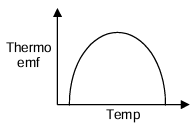
Such a combination of two metals is called a thermocouple. The graph shows the nature of variation of the thermo emf with the temperature of the hot junction. If the temp of the cold junction is 0°C and the hot junction be at θ°C, then the thermo-emf is given by
ε = aθ + (1/2)bθ²
When a and b are the constants for a given pair of metals which constitute the thermocouple.
Thermoelectric Series
The sequence of metals arranged in a series which is used to predict the direction of current in a thermocouple in the temperature range 0°C to 100°C is called the thermoelectric series. Antimony, Nichrome, iron, zinc, copper, gold silver lead, aluminum mercury, platinum-rhodium, platinum, nickel, constantan, bismuth. The direction of current at the cold junction is from the metal coming earlier in the series.
Thermoelectric power:
Differentiating E with respect to temperature θ,
dE/dθ = a + bθ
The quantity dE/dθ is called the thermoelectric power P at temperature θ.
Thus P = a + bθ represents the equation of a straight line which is called a thermoelectric line.
Neutral Temperature: θₙ and temperature of inversion θᵢ:
The temperature of the hot junction at which the thermo emf is maximum is called the neutral temperature (θₙ). Thus at neutral temperature dE/dθ = 0 ∴ θₙ = -a/b.
The temperature of the hot junction at which the thermo-emf changes its sign (direction of thermo-current is reversed) is called the temperature of inversion θᵢ. If θc = temperature of the cold junction, then
θₙ - θc = θᵢ - θₙ
Example: If the temperature of the cold junction is maintained constant at 10°C and the thermo-emf is reduced to zero at 440°C then find the neutral temp θₙ and the temperature of inversion θᵢ.
Solution: Since emf is zero at θᵢ,
we have θᵢ = 440°C
Again θᵢ - θₙ = θₙ - θc
θₙ = (θᵢ + θc)/2 = (440 + 10)/2
= 225°C
Formulae And Concepts At A Glance
- Current density (J) = I/A = neVd = σE where σ = neμ (σ = conductivity and μ = mobility)
- Drift velocity Vd = eEτ/m, where τ is relaxation time E is electric field and m is mass of electron.
- To convert a galvanometer (or coil) of maximum current Ig and internal resistance Rg into an ammeter, to measure the current I, a shunt S be connected in parallel S = RgIg/(I-Ig)
- To convert a galvanometer (or coil) of maximum current Ig and internal resistance Rg into an voltmeter, in order to measure V volts, a resistance R be connected in series where R = V/Ig - Rg
- An ideal ammeter has zero resistance and an ideal voltmeter has infinite resistance.
- Faraday's law of electrolysis: a) m = zIt b) m₁/m₂ = z₁/z₂ = E₁/E₂
- Tₙ (neutral temperature) temperature of hot junction for which a generated emf is maximum emf E = αt + (1/2)βt², t = Tₙ if dE/dθ = 0
Solved Problems
Problem 1: The effective resistance between the point A and B will be
(A) 4Ω
(B) 2Ω
(C) 6Ω
(D) 8Ω
Solution: Resistors AF and FE are in series with each other. Therefore, network AEF reduces to a parallel combination of two resistors of 6Ω each.
Req. = (6 × 6)/(6 + 6) = 3Ω.
Similarly, the resistance between A and D is given (6 × 6)/(6 + 6) = 3Ω.
Now, resistor AC is in parallel with the series combination of AD and DC.
Therefore, the resistance between A and C is (6 × 6)/(6 + 6) = 3Ω. AC + CB = 3 + 3 = 6Ω.
Since they are in series resistance between A and B is given by 1/R = 1/6 + 1/3 = 3/6 or R = 2Ω.
Hence (B) is correct answer.
Problem 2: A 3 volt battery with neglible internal resistance is connected in a circuit as shown in figure. The current I in the circuit will be
(A) 1/3 A
(B) 1A
(C) 1.5 A
(D) 2A
Solution: Equivalent resistance of the circuit R = (3 × 3)/(3 + 3) + (3 × 3)/(3 + 3) = 6/6 + 6/6 = 2Ω
I = V/R = 3/2 = 1.5A
Hence (C) Is Correct Answer
Problem 3: The current in a wire varies with time according to the equation I = 4 + 2t, where I is in ampere and t is in sec. The quantity of charge which has passed through a cross-section of the wire during the time t = 2 sec to t = 6 sec will be
(A) 60 coulomb
(B) 24 coulomb
(C) 48 coulomb
(D) 30 coulomb
Solution: Let dq be the charge which has passed in a small interval of time dt,
then dq = idt = (4 + 2t)dt Hence total charge passed between interval t = 2 sec and t = 6 sec
q = ∫₂⁶ (4 + 2t)dt = 48 coulomb ∴ (C)
Problem 4: The resistance of the series combination of two resistances is S. When they are joined in parallel the total resistance is P. If S = np, the, the minimum possible value of n is
(A) 4
(B) 3
(C) 2
(D) 1
Solution: Here S = R₁ + R₂ and P = (R₁R₂)/(R₁ + R₂)
S/P = (R₁ + R₂)²/(R₁R₂) = (R₁/R₂) + 2 + (R₂/R₁)
Let X= R₁/R₂
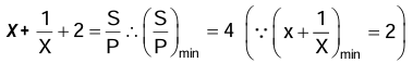
Hence (A) is correct answer.
Problem 5: A electric current of 16 A exists in a metal wire of cross section 10⁻⁶ m² and length 1m. Assuming one free electrons per atom, the drift speed of the free electrons in the wire will be (Density of metal =5 × 10³ kg/m³, atomic weight = 60)
(A) 5 × 10⁻³ m/s
(B) 2 × 10⁻³ m/s
(C) 4 × 10⁻³ m/s
(D) 7.5 × 10⁻³ m/s
Solution: According to Avogadro's hypothesis N/NA = m/M so n = N/V = (NAm)/(VM)
Hence total number of atoms n = (6 × 10²³ × 5 × 10³)/(60 × 10⁻³) = 5 × 10²⁸ /m³
As I = neᵥdA
Hence drift velocity vd = I/(neA)
vd = 16/(5 × 10²⁸ × 1.6 × 10⁻¹⁹ × 10⁻⁶) = 2 × 10⁻³ m/s
Hence (B) is correct answer.
Problem 6: A copper wire is stretched to make it 0.1 % longer. The percentage change in its resistance is
(A) 0.2 % increase
(B) 0.2% decrease
(C) 0.1 % increase
(D) 0.1 % decrease
Solution: For a given wire, R = ρL²/V with L × s = volume =
V = constant
so that R = ρL²/V
ΔR/R = 2ΔL/L
= 2 (0.1 %)
= 0.2 % (increase)
Hence (A) is correct answer.
Problem 7: The mass of the three wire of copper are in the ratio 1 : 3 : 5. and their lengths are in ratio 5 : 3 : 1. The ratio of their electrical resistance is
(A) 1 : 3 : 5
(B) 5 : 3 : 1
(C) 1 : 15 : 125
(D) 125 : 15 : 1
Solution: R = ρℓ²/(A²) = ρℓ²/(V) = ρℓ²d/(m/ρd)
R = ρℓ²/m or R ∝ ℓ²/m
R₁ : R₂ : R₃ = (ℓ₁²/m₁) : (ℓ₂²/m₂) : (ℓ₃²/m₃) = (25/1) : (9/3) : (1/5) = 125 : 15 : 1
Hence (D) is correct answer.
Problem 8: A battery of 10 volt is connected to a resistance of 20 ohm through a variable resistance R. The amount of charge which has passed in the circuit in 4 minutes, if the variable resistance R is increased at the rate of 5 ohm/min.
(A) 120 coulomb
(B) 120 loge2 coulomb
(C) 120/loge2 coulomb
(D) 60/loge2 coulomb
Solution: I = V/R
dq/dt = V/R
dq/dR × dR/dt = V/R
dq = 12 V dR/R
q = 12 V ∫₂₀⁴⁰ dR/R = 12 V (loge 40 – loge20)
= 12 × 10 × loge2 ∴ (B)
Problem 9: In the given circuit, R₁ = 10Ω, R₂ =6Ω and E = 10 V correct statement are
(A) Effective resistance of the circuit is 20Ω
(B) Reading of A₁ is 2 amp
(C) Reading of A₂ is 4 amp
(D) Reading of A₃ is 1/8 amp.
Solution: Potential difference across R₂ resistances is zero, therefore current in three branches is zero, therefore current in two branch containing R₁ will be same, simplified circuit will be
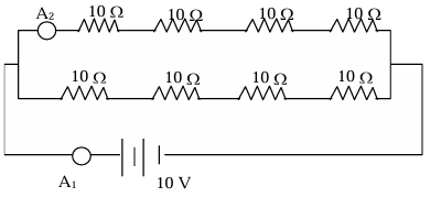
Effective resistance of the circuit Reff = (40 × 40)/(40 + 40) = 20Ω current through the circuit I = 10/20 = (1/2) amp
Hence reading of A₁ = ½ amp.
Hence reading of A₂ =1/4 amp.
Hence (A) is correct answer.
Problem 10: One billion electrons pass from A to B in 1 ms. What is the direction and magnitude of current?
(A) 1.6 μA
(B) 0.8 μA
(C) 0.16 μA
(D) 1.6 μA
Solution: i = Ne/t = (10⁹)(1.6×10⁻¹⁹ C)/(10⁻³) = 1.6×10⁻⁷ A
i = 0.16 μ A. The current flows from B to A.
Hence (C) is correct answer.