Electromagnetic Induction: The Foundation of Modern Electrical Technology
Electromagnetic induction represents one of the most fundamental principles in physics, discovered by Michael Faraday through systematic experimentation in the 1830s. This phenomenon occurs whenever there is relative motion between a magnetic field and a conducting loop, resulting in the generation of an electric current without any physical electrical connection.
The principle of electromagnetic induction underlies virtually all modern electrical power generation, from massive hydroelectric generators to small electric motors. When a magnetic field changes in the vicinity of a conductor, it creates an electric field that drives current through the conductor, converting mechanical energy into electrical energy.
Faraday's Law: The Mathematical Foundation
Faraday's Law of Electromagnetic Induction provides the quantitative relationship for induced electromotive force (EMF). The law states that the magnitude of induced EMF is directly proportional to the rate of change of magnetic flux through a conducting loop.
Magnetic flux represents the total magnetic field passing through a given area and depends on several factors: the strength of the magnetic field, the area of the conductor, and the angle between the field lines and the surface normal. The mathematical expression φ = NBA cos θ captures this relationship, where N represents the number of turns in a coil, B is the magnetic field strength, A is the area, and θ is the angle between the field and area vector.
The induced EMF can be calculated using ε = -dφ/dt, where the negative sign indicates the direction of the induced EMF according to Lenz's Law. This relationship demonstrates that faster changes in magnetic flux produce larger induced voltages, explaining why rapidly spinning generators produce higher voltages than slowly rotating ones.
Lenz's Law: Nature's Opposition to Change
Lenz's Law provides the directional aspect of electromagnetic induction, stating that induced currents flow in a direction that opposes the change causing them. This law represents a specific application of energy conservation - if induced currents aided the change causing them, it would create a perpetual motion machine violating fundamental physical principles.
When a magnet approaches a conducting loop, the induced current creates a magnetic field that opposes the magnet's motion. Conversely, when the magnet moves away, the induced current creates a field that tries to prevent this separation. This opposition ensures that energy is conserved throughout the induction process.
Motional EMF and Practical Applications
Motional EMF occurs when a conductor moves through a magnetic field, with the magnitude given by ε = Bvℓ for perpendicular motion, where B is the magnetic field strength, v is the velocity, and ℓ is the length of the conductor. This principle operates in applications ranging from electric generators to velocity sensors.
In power generation, rotating coils in magnetic fields produce sinusoidal voltages that form the basis of alternating current (AC) electrical systems. The frequency and amplitude of the generated voltage depend on the rotation speed, magnetic field strength, and coil geometry.
Inductance: The Magnetic Analog of Capacitance
Inductance quantifies a conductor's ability to store magnetic energy, similar to how capacitance measures electric energy storage. Self-inductance (L = φ/I) describes how a conductor's own magnetic field affects its electrical behavior, while mutual inductance characterizes the magnetic coupling between separate conductors.
The energy stored in an inductor equals ½LI², demonstrating that magnetic energy storage increases quadratically with current. This relationship proves crucial in power electronics, where inductors smooth current fluctuations and store energy for later release.
For solenoids, inductance depends on geometry through L = μ₀n²ℓA, where n represents turns per unit length, ℓ is the solenoid length, and A is the cross-sectional area. This formula reveals that inductance increases with the square of turn density, explaining why high-inductance coils require many closely-wound turns.
R-L Circuits: Transient Behavior and Time Constants
R-L circuits exhibit exponential behavior during current changes, with growth described by I = (ε/R)(1 - e^(-Rt/L)) and decay by I = I₀e^(-Rt/L). The time constant τ = L/R determines how quickly these changes occur, with larger inductances creating slower transitions.
This exponential behavior appears in numerous applications, from motor startup characteristics to switching power supply design. Understanding R-L transients proves essential for predicting circuit behavior during switching events and designing appropriate protection schemes.
L-C Oscillations: The Foundation of Resonant Circuits
L-C circuits demonstrate pure oscillatory behavior with frequency f = 1/(2π√LC), where energy alternates between magnetic storage in the inductor and electric storage in the capacitor. These oscillations form the basis for radio frequency circuits, filters, and timing circuits.
The total energy remains constant during oscillation, equal to ½CV₀² = ½LI₀², where V₀ and I₀ represent maximum voltage and current values. This energy conservation principle enables precise frequency control in electronic systems.
Essential Electromagnetic Induction Formulas
| Formula Name | Mathematical Expression | Description |
|---|---|---|
| Magnetic Flux | φ = ∫B⋅dA = NBA cos θ | Total magnetic field through an area |
| Faraday's Law | ε = -dφ/dt | Induced EMF from changing flux |
| Motional EMF | ε = Bvℓ | EMF from conductor motion in magnetic field |
| Self Inductance | L = φ/I | Magnetic flux per unit current |
| Mutual Inductance | φ₂ = MI₁ | Flux in coil 2 due to current in coil 1 |
| Inductor Energy | E = ½LI² | Magnetic energy stored in inductor |
| Solenoid Inductance | L = μ₀n²ℓA | Inductance of ideal solenoid |
| LC Frequency | f = 1/(2π√LC) | Natural oscillation frequency |
| R-L Growth | I = (ε/R)(1 - e^(-Rt/L)) | Current growth in R-L circuit |
| R-L Decay | I = I₀e^(-Rt/L) | Current decay in R-L circuit |
Applications and Modern Relevance
Electromagnetic induction principles enable countless modern technologies. Electric generators convert mechanical energy to electrical energy in power plants, while transformers efficiently transfer electrical energy between different voltage levels. Electric motors reverse the process, converting electrical energy to mechanical work.
Modern applications extend beyond traditional power systems to include wireless charging, magnetic levitation systems, and non-contact sensors. Understanding electromagnetic induction remains crucial for engineers designing everything from smartphone chargers to magnetic resonance imaging systems.
The principles established by Faraday continue driving technological innovation, demonstrating the enduring importance of fundamental electromagnetic theory in practical applications. As renewable energy systems and electric vehicles become increasingly prevalent, electromagnetic induction knowledge proves more valuable than ever for students and practicing engineers alike.
Electromagnetic Induction
We can draw many conclusions on the basis of symmetry. In previous chapter we studied the effect of magnetic field on current carrying conductor. When a current loop is placed in a magnetic field it experiences a torque, that rotates it. From symmetry we can say that if a conducting loop is made to rotate in a magnetic field, current should appear in the loop and it happens.
First of all this fact was observed by Michael Faraday. On the basis of his several experimental observations he came to the conclusion that:
- Whenever there is a relative motion between a magnet (source of magnetic field) and a closed conducting loop, electric current appears in the loop. It happens because of change in magnetic flux associated with the loop.
- Since e.m.f. causes current in the circuit, when loop and magnet are brought in relative motion current flows in the loop. This implies that an emf is set up in the loop. This emf is known as induced emf and its magnitude is directly proportional to the rate of change of magnetic flux with time.
Magnetic Flux
Now we must know about the magnetic flux.
Magnetic flux associated with any area is given by the expression:
ΦB = ∫s B⃗ · ds⃗
Here B⃗ is the magnetic field and ds⃗ is area element. Area is taken as a vector quantity and its direction is perpendicular to surface.
Flux associated with plane coil having N turns in a uniform magnetic field B⃗ is equal to:
ΦB = N(B⃗ · A⃗) = NBA cos θ
Here:
- N = number of turns in the loop
- B = magnetic field strength
- A = area of the loop
- θ = angle between area vector and magnetic field
Faraday's Law of Electromagnetic Induction
Now we come to the Faraday's law of electromagnetic induction in mathematical form. Induced emf can be given by the expression:
ε = -dΦB/dt
As such Faraday's law in itself is complete to tell the magnitude and polarity of induced emf, it is the Lenz's rule that is commonly used to determine the polarity of induced emf or direction of induced current.
Magnetic flux associated with a loop can be changed by various method. By changing N, by changing B, by changing A or by changing the angle between A⃗ and B⃗.
Illustration: A conducting circular loop of radius 5.0 cm is placed perpendicular to a magnetic field of 0.50 T. It is removed from the field in 0.5 sec. Find the average emf induced in the loop during this time.
Solution:
Radius = 5.0 cm = 5 × 10⁻²m
B = 0.5 T
time taken = 0.50 sec.
Change in flux = (0.5 × π × 25 × 10-4) - 0
Emf induced = (0.5 × π × 25 × 10-4)/0.50
= 7.8 × 10⁻³ V
Lenz's Law
It states that induced emf opposes the cause due to which it has been induced
Consider the following examples:
(a) Magnet Moving Towards Loop
Suppose north-pole of a bar magnet is moved towards a loop as shown in the figure. Because of change in magnetic flux associated with the loop current is induced in it. Due to induced current magnetic field is induced in such a way that it opposes the motion of bar magnet. As north pole is moving towards the loop hence to oppose the motion of the bar magnet only north pole will be induced on that face of the loop which faces the magnet.
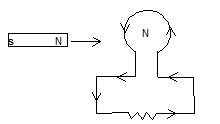
[N] ← [S N]
(b) Loop Moving Out of Magnetic Field
Consider the figure shown. A rectangular loop ABCD is being pulled out of the magnetic field directed into the plane of the paper and perpendicular to the plane of the paper. As the loop is dragged out of the field the flux associated with the loop which is directed into the plane of the paper decreases. The induced current will flow in the loop in the sense to oppose the decreasing of this flux. For this to be happen magnetic field due to induced current in the loop must be directed into the plane of the paper. Hence current in the loop must flow in the clockwise sense.
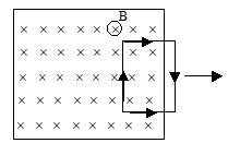
Motional E.M.F.
If a conductor is moving in a magnetic field electrons inside it, experience a force F⃗ = e(v⃗ × B⃗) and accumulate at the end of the conductor. Very soon, an electric field is established. Eventually component of magnetic force along the conductor length is balanced by the electric field force and the drifting of electrons stop giving an emf.
Now,
ε = ∫ E⃗ · dl⃗ = ∫ (v⃗ × B⃗) · dl⃗
This is the general expression for induced emf in a conducting wire. If v⃗ and B⃗ are mutually perpendicular to each other then ε = Bvl.
Illustration: A conducting loop of area 5.0 cm² is placed in a magnetic field which varies sinusoidally with time as B = B₀ sin ωt (B₀ = 0.20T and ω = 300/sec). The normal to the coil makes an angle of 0° with the field. Find the maximum emf induced in the coil and the emf induced at t = π/600 sec.
Solution:
A = Area of loop = 5.0 × 10⁻⁴ m²
B⃗ = B₀ sin ωt
ω = 300 Hz
B₀ = 0.2 T
Flux through the coil = BA
Emf induced = -d(BA)/dt = -A(dB/dt)
Maximum emf induced = A|dB/dt|max = A|B₀ω cos ωt|max
= AB₀ω = 5 × 10-4 × 0.2 × 300 = 3 × 10⁻² V
Emf induced at t = π/600 sec.
= -5 × 10-4 × 0.2 × 300 × cos(300 × π/600) = 0
Illustration:
A metal rod 1.5 m long rotates about its one end in a vertical plane at right angles to the magnetic meridian. If the frequency of rotation is 20 rev/s. Find the emf induced between the ends of rod.
BH = 0.32 × 10⁻⁴T: Horizontal component of earth's magnetic field.
Solution:
Length of rod = 1.5 m.
Frequency of rotation = 20 rev/sec.
BH = 0.32 × 10⁻⁴ T
Angular velocity of rod = 20 × 2π rad/sec.
Emf induced = BH × (dA/dt) = 0.32 × 10-4 × 20 × π × (1.5)² = 4.5 × 10⁻³ V
Exercise 1: An air plane with 20m wing spread is flying at 250 m/s straight along south parallel to the earth surface. The earth's magnetic field has a horizontal component of 2 × 10⁻⁵ Wb/m² and the dip angle is 60°. Calculate the induced emf. between the wing tips.
Inductor
Already we have studied about capacitor – that stores energy in the form of electric field. Like capacitor, inductor is also quite a commonly used element in electric circuits, which stores magnetic energy. Inductance of an inductor depends on its geometry and medium in which it lies. As we know that when current flows through a conductor a magnetic field is set-up in surrounding of it, and hence it is associated with magnetic flux. If magnetic flux associated with a coil is Φ and current in it is I, then its inductance is given by the expression:
L = Φ/I
'L' is called self-inductance of the coil.
S.I. unit of inductance is Henry.
The magnetic energy stored in an inductor is given by:
E = ½LI²
Self Inductance
Consider the circuit, in which a solenoid is connected across a cell through a resistor. When switch is open current in the circuit is zero. When switch is closed current flows in it. Since current in the circuit increases from zero to certain value, magnetic field associated with it changes that causes induction of an e.m.f. in the solenoid.
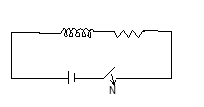
Induction of an e.m.f. due to variation of current in the coil itself is known as self induction.
Since ΦB = LI, and
ε = -dΦB/dt = -L(dI/dt)
The inductance of an ideal solenoid is given by:
L = μ₀n²Al
where n = no. of turns per unit length,
l = length of solenoid
A = Area of solenoid.
Mutual Inductance
Two coils C₁ and C₂ are placed very close to each other. A source of emf is connected in the coil C₁. When current flows through the coil C₁ magnetic field is induced. The coil C₂ lies within the magnetic field of C₁ and hence magnetic flux is associated with it. So long current changes in the coil C₁ its magnetic field changes and hence flux associated with C₂ also changes, which causes the inductance of an emf. in the coil.
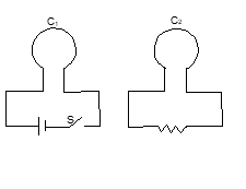
Induction of an emf due to variation of current in the neighbouring coil is known as mutual induction.
Flux associated with C₂ depends on current in C₁ and no. of turns in C₂.
ΦB(C₂) = MI₁
Where M is the mutual inductance of the pair.
ε = -dΦB/dt = -M(dI₁/dt)
SI unit of mutual inductance is Henry.
Illustration: What is the self inductance of a system of co-axial cables carrying current in opposite directions as shown. Their radii are 'a' and 'b' respectively.
Solution:
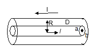
The 'B' between the space of the cables is
B = μ₀I/2πr
The Ampere's law tells that 'B' outside the cables is zero, as the net current through the amperian loop would be zero.
Taking an element of length l and thickness 'dr', dΦ through it is
dΦ = (μ₀Il/2π) × (dr/r)
Φ = ∫ᵃᵇ (μ₀Il/2π) × (dr/r) = (μ₀Il/2π) × ln(b/a)
L = Φ/I = (μ₀l/2π) × ln(b/a)
R-L Circuit
- Growth of Current:
A series combination of an inductor L and a resistor R are connected across a cell of e.m.f. ε through a switch S as shown.

When switch is closed current starts increasing in the inductor. This causes an induction of e.m.f. in the inductor. The current in circuit at any time t is given by:
I(t) = (ε/R) × [1 - e(-Rt/L)]
Here, It represents the instantaneous current in the circuit.
- Decay of Current:
In this case source of emf is disconnected from the circuit. In this case:
I(t) = I₀ × e^(-Rt/L)
(L/R) is called time constant as its dimension is same as that of time.
Illustration: A conducting circular loop with variable radius r is placed in a uniform magnetic field B=0.020T with plane perpendicular to the field. While the radius of the loop is contracting at a constant rate of 1.0 mm/s; Find the induced emf in the loop when the radius is 2 mm.
Solution:
Radius (variable) = r
B = 0.02 T
Induced emf E = -d(BA)/dt = -B × (dA/dt) = -B × 2πr × (dr/dt)
dr/dt = -1.0 × 10⁻³ m/s
r = 2 × 10⁻³ m
E = 0.02 × 2π × 2 × 10-3 × 1 × 10-3
= 6π × 10-8 = 18.85 × 10⁻⁸ V.
Illustration: A coil of inductance 1.0 H and resistance 100 Ω is connected to a battery of emf 12 V. Find the energy stored in the magnetic field of coil 10 ms after the circuit is switched on.
Solution:
L = 1.0 H
R = 100 Ω
E = 12 V
i(t) = (E/R) × [1 - e^(-Rt/L)]
Energy stored in the magnetic field is ½ L i².
= ½ × 1.0 × [(12/100) × (1 - e^(-100×10×10⁻³/1))]²
= ½ × 144/10⁴ × (1 - e^(-1))² = 28.8 mJ
Exercise 2: Referring to the previous Illustration find the energy stored in the inductor when the current I is dropped to a value of 5mA.
L.C. Oscillations
A capacitor is charged to a p.d. of V₀ by connecting it across a battery and then is allowed to discharge through a pure inductor of inductance L, oscillations are produced.
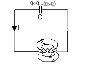
The frequency of the oscillations can be given by:
f = 1/(2π√(LC))
The charge q on the plates of the capacitor and current I in the circuit vary sinusoidally as:
q = q₀ sin (ωt + φ) and I = q₀ω cos (ωt + φ)
where φ is the initial phase and it depends on initial situation of the circuit
ω = 1/√(LC)
The total energy of the system remains conserved:
½CV² + ½LI² = constant = ½CV₀² + ½LI₀²
Illustration: A capacitor of capacity 2μF is charged to a potential difference of 12V. It is then connected across an inductor of inductance 0.6 mH. What is the current in the circuit at a time when the potential difference across the capacitor is 6.0V?
Solution:
As the capacitor is charged to a p.d. of 12V, the initial charge on the capacitor is q₀ = CV₀ = 2 × 10-6 × 12 Coul. ——— (1)
At any instant as the capacitor discharges through the inductor (LC circuit), the instantaneous charge on the capacitor is given by
q = q₀ cos ωt ——— (2) [because at t = 0, q = q₀]
But q = CV ——— (3) where V is the p.d. at the instant 't'.
From (1) and (3) we obtain q/q₀ = V/V₀
Putting the value of V and V₀ we obtain, q/q₀ = 1/2
cos ωt = 1/2
ωt = cos-1(1/2) = π/3 rad. ——— (4)
Here ω = 1/√(LC) = 1/√(0.6×10-3 × 2×10-6) = 2√3 × 10⁵ rad/sec. ——— (5)
The current through the circuit at that instant is given by,
i = -dq/dt = q₀ω sin ωt
Putting the value of q₀ from (1), ω from (5) and ωt from (4) we obtain.
i = 12 × 2 × 10-6 × 2√3 × 10⁵ × sin(π/3)
= |i| = 0.6 A
Exercise 3: A capacitor discharges through an inductor of 0.1 Henry. If the frequency of discharge is 1000 Hz. Calculate the capacitance.
Formulae and Concepts at a Glance
- ΦB = ∫ B⃗ · ds⃗ = NBA cos θ
- ε = -dΦ/dt
- When a coil of length l is moving in a magnetic field B with velocity v, then
ε = ∫ (v⃗ × B⃗) · dl⃗ - For a long solenoid L = μ₀n²Al
- Magnetic energy stored in an inductor E = ½LI²
Solved Examples
Problem 1:
An aeroplane with wings span of 50m flies at 540 km/hr. The component of the earth's magnetic field perpendicular to the velocity of the plane is 0.2 gauss. The potential difference between is
- (A) 0.15V
- (B) 1.5V
- (C) 15V
- (D) 150V
Solution:
ε = Bℓv
= 0.2×10−4 × 50×150 V {v = 540/(18/5) m/s, 1 gauss = 10−4}
= 0.15 V
∴ (A)
Problem 2:
Which of the following can produce the maximum induced emf?
- (A) 1A, D.C.
- (B) 50A, D.C
- (C) 1A, 60Hz A.C.
- (D) 1 Amp, 400Hz A.C.
The D.C. does not produce induced emf.
ε = −L dI/dt
dt is small for large f. Hence (D) is correct.
Problem 3:
The magnetic energy in Joules stored in a 10H inductor carrying a current of 3 Amp is
- (A) 15J
- (B) 30J
- (C) 45J
- (D) 90J
Energy stored, U = ½LI² = ½ ×10×3² = 45J
∴ (C)
Problem 4:
Two circuits have coefficient of mutual inductance of 0.09H. What average e.m.f. is induced in the secondary by a change from 0 to 20A in 0.006 sec in the primary?
- (A) 120V
- (B) 180V
- (C) 200V
- (D) 300V
|ε| = M dI/dt = 0.09 × (20 / 0.006) = 300V
∴ (D)
Problem 5:
An electron moves along the line AB which lies in the same plane as a circular loop of conducting wire as shown in the diagram. What will be the direction of the current induced, if any, in the loop?
- (A) No current will be induced.
- (B) The current will be clockwise.
- (C) The current will be anti-clockwise.
- (D) The current will change direction as the electron passes.
[Diagram: electron passes AB beside wire loop]
According to Lenz's law, a current in the circular loop will be set up in such a way as to oppose the motion of the electron. For this a force in direction BA should act on the electron. So the current should be clockwise.
∴ (B)
Problem 6:
A conducting loop is placed and pulled with constant velocity towards a region of constant (steady) magnetic field of induced B as shown in the figure. Then the current involved in the loop is (d > r)
- (A) clockwise.
- (B) anticlockwise
- (C) zero
- (D) All of these.
[Diagram: conducting loop near magnetic field region with symbols]
When the loop is drawn into the magnetic field, the area of the portion of the loop in the magnetic field increases. Therefore an (anticlockwise) emf is induced so as to oppose the change. After the complete entrance of the loop into the magnetic field, no variation of flux occurs. Therefore it induces no current so long as the loop is completely inside the magnetic field. When it emerges out of the magnetic field, the direction of induced emf will be clockwise.
∴ (D)
Problem 7:
Two identical coaxial circular loops carry a current i, each circulating in the same direction. If the loops approach each other, then
- (A) the current in each will decrease.
- (B) the current in each will increase.
- (C) there will be no change of current.
- (D) the current will increase in one and decrease in other.
The magnetic field due to current in each loop will oppose each other. Thus the current will decrease in both the loops.
∴ (A)
Problem 8:
A D.C. dynamo develops 220V emf at 100rpm and 10A field current. What emf does it develop at 1200 rpm and 5A field current?
- (A) 124V
- (B) 132V
- (C) 144V
- (D) 152V
E ∝ If × f
E = (1200 × 5) / (100 × 10) × 220 = 132V
∴ (B)
Problem 9:
The magnetic flux through a loop of resistance R = 0.2Ω is varying according to the relation ϕB = 6t² + 7t + 1, where ϕB is in milli webers and t is in seconds. The magnitude of EMF after t = 2s is
- (A) 28mV
- (B) 29mV
- (C) 30.5mV
- (D) 31mV
ϕB = (6t² + 7t + 1) × 10−3 Wb
e (induced emf) = dϕB/dt = (12t + 7) × 10−3 Volt
at t = 2s, e = (12×2+7) × 10−3 V = 31 mV
∴ (D)
Problem 10:
A metal rod of length 1m is held at an angle of 30° with a horizontal magnetic field of induction 0.5Wb/m². It is then moved parallel to itself downward at speed of 4 m/s. The induced emf across it is
- (A) 1.0V
- (B) 1.5V
- (C) 2.0 V
- (D) 1.732V
The component of the field perpendicular to the rod is effective in producing the induced emf.
ε = BℓV sinθ = 0.5×1×4×sin30° = 1V
∴ (A)