Understanding Optics: From Wave Theory to Practical Applications
Optics represents one of the most fundamental branches of physics, governing how light behaves and interacts with matter. This electromagnetic radiation, visible to human eyes within the wavelength range of 400-700 nanometers, exhibits both wave and particle properties that form the foundation of modern optical science.
Wave Nature of Light and Huygen's Principle
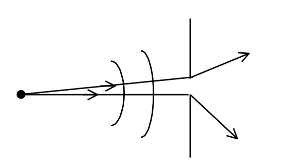
The wave theory of light, established through Huygen's principle, demonstrates that each point on a wavefront acts as a source of secondary wavelets. These wavelets propagate at light speed through uniform media, with their envelope determining the new wavefront position. This fundamental concept explains critical optical phenomena including interference and diffraction patterns.
Light waves consist of oscillating electric and magnetic fields, mathematically expressed as E = E₀[sin(ωt - kx + φ₀)], where ω represents angular frequency, k denotes the wave number, and φ₀ indicates initial phase. Understanding this wave equation proves essential for analyzing interference patterns and optical instrument performance.
Points to remember regarding Interference
-
When two waves with amplitude A1 and A2 superimpose at a point, the amplitude of resultant wave is given by
A = √(A12 + A22 + 2 A1 A2 cos φ)
Where φ is the phase difference between the two waves at that point.
- Intensity (I) = 1⁄2μ0c E02. c = speed of light,E0 = electric field amplitude
- Intensity (I) = I1 + I2 + 2 √(I1I2) cos φ.
Hence for I to be constant, φ must be constant.
- When φ changes arbitrarily at a point, the intensity = I1 + I2.
- When φ does not change with time, we get an intensity pattern and the sources are said to be coherent.
Coherent sources have phase relationship that does not change with time.
-
The intensity at a point becomes a maximum when φ = 2nπ (n = 0, 1, 2, ...) and there is constructive interference.
-
If φ = (2n − 1)π there is destructive interference. (Here n is a non-negative integer)
Determination of Phase Difference
The phase difference between two waves at a point will depend upon
- the difference in path lengths of the two waves from their respective sources.
- the refractive index of the medium.
- initial phase difference, between the source, if any.
- Reflections, if any, in the path followed by waves.
In the case of light waves, the phase difference on account of path difference
Optical path difference / λ × 2π = μ (Geometrical path difference) / λ × 2π
where λ is the wavelength in free space.
In the case of reflection, the reflected disturbance differs in phase by π with respect to the incident one if the wave is incident on a denser medium from a rarer medium. No such change of phase occurs when the wave is reflected in going from a denser medium to a rarer medium.
Interference Phenomena and Young's Double Slit Experiment
Interference occurs when two or more light waves superimpose, creating regions of constructive and destructive interference. The resultant amplitude follows the relationship A = √(A₁² + A₂² + 2A₁A₂cos φ), where φ represents the phase difference between interfering waves.
Young's double slit experiment demonstrates wave interference through parallel slits separated by distance 'd'. The phase difference φ = (2π/λ)(dy/D) determines bright and dark fringe positions, where constructive interference produces maxima at φ = 2nπ and destructive interference creates minima at φ = (2n-1)π.
Important Note: Fringe width calculation follows W = λD/d, where λ represents wavelength, D indicates screen distance, and d denotes slit separation. This relationship enables precise wavelength measurements and validates wave theory predictions.
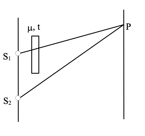
A train of plane light waves is incidenting on a barrier into which are cut two narrow slits separated by a distance 'd'. The width of the slits are small compared with wavelength of the light used, so that interference occurs in the region where the light from S1 overlaps that from S2. A series of alternately bright and dark bands can be observed on a screen placed in this region of overlap.
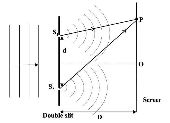
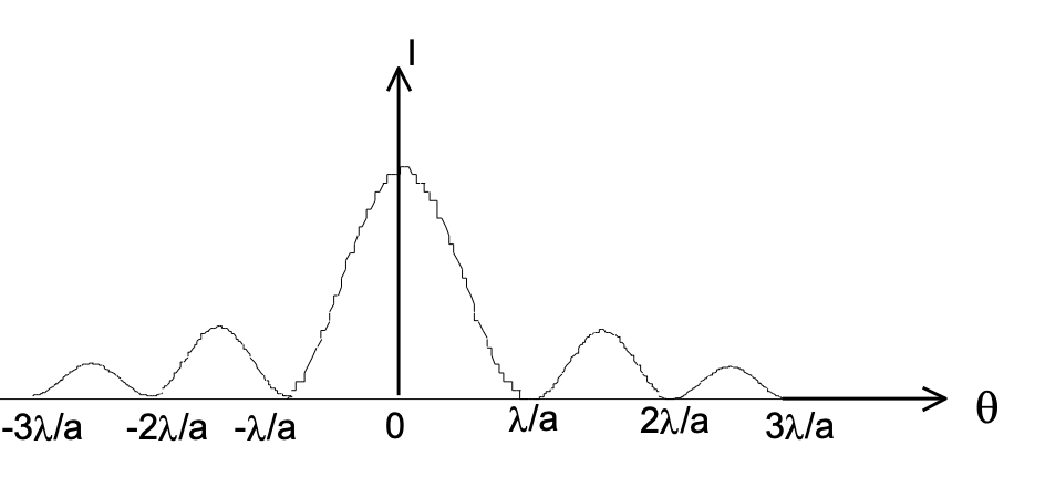
The variation in light intensity along the screen near the centre O is shown below. Now consider a point P on the screen. The phase difference between the waves at
P = φ (say)
= (2π/λ) ΔPo
(where ΔPo is optical path difference, ΔPo = ΔPg; ΔPg being the geometrical path difference.)
= (2π/λ) [S2P – S1P] (here μ = 1 in air)
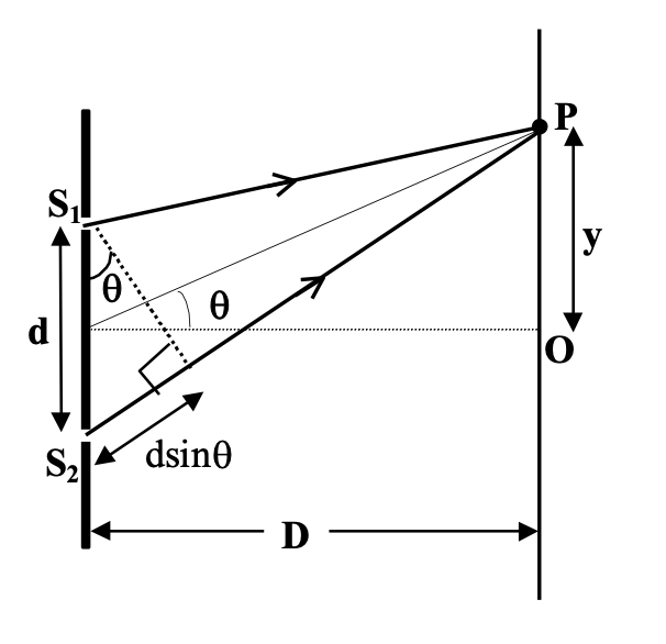
As D >> d,
S2P – S1P ≈ d sinθ
sinθ ≈ tanθ (= y/D).
[for very small θ]
Thus, φ = (2π/λ) (dy/D)
For constructive interference,
φ = 2nπ (n = 0, 1, 2 …)
⇒ (2π/λ) (dy/D) = 2nπ
⇒ y = n λD/d
Similarly for destructive interference,
y = (2n − 1) ( λD/ 2d) (n = 1, 2, …)
Fringe Width W
It is the separation of two consecutive maximas or two consecutive minimas.
Near the centre O [where θ is very small],
W = yn+1 − yn [yn gives the position of nth maxima on screen] = λD/ d
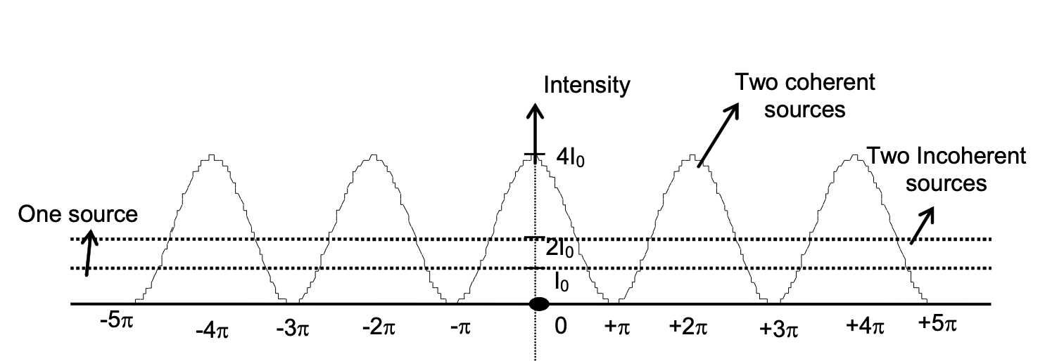
Intensity Variation on Screen
If A and I0 represent the amplitude of each wave and the associated intensity on the screen, then the resultant intensity at a point on the screen corresponding to the angular position θ (as in the figure) is given by
I = I1 + I2 + 2√(I1I2) cos φ
where φ = (2π d sin θ)/λ.
For equal sources I1 = I2 = I0:
I = 4 I0 cos2(φ/2)
Displacement of Fringes
When a film of thickness t and refractive index μ is introduced in the path of one of the source’s light, then fringe shift occurs as the optical path difference changes.
Optical path difference at
P = S2P − [ S1P + μt − t ] = S2P − S1P − (μ − 1)t = (y · d) / D − (μ − 1)t
⇒ nth fringe is shifted by
Δy = D(μ − 1)t / d = (w / λ)(μ − 1)t
where w is the fringe width, w = Dλ/d.
Diffraction
Diffraction is the bending or spreading of waves that encounter an object ( a barrier or an opening) in their path. In Fresnel class of diffraction, the source and/or screen are at a finite distance from the aperture.
In Fraunhoffer class of diffraction, the source and screen are at infinite distance from the diffracting aperture. Fraunhoffer is a special case of Fresnel diffraction.
Single Slit Fraunhoffer Diffraction
In order to find the intensity at point P on the screen as shown in the figure the slit of width 'a' is divided into N parallel strips of width Δx. Each strip then acts as a radiator of Huygen's wavelets and produces a characteristic wave disturbance at P, whose position on the screen for a particular arrangement of apparatus can be described by the angle q.
The amplitudes ΔEo of the wave disturbances at P from the various strips may be taken as equal if qis not too large. The intensity is proportional to the square of amplitude. If Im represent the intensity at O, its value at P is
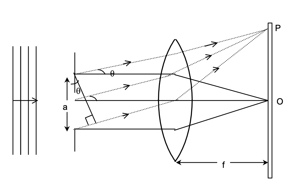
Iθ=Im(sinα/α)2;
where
α= ϕ/2 =πasinθ/λ
Minima occurs when, sinα=0 and α≠0, so α=nπ, n=1,2,3,…
⇒ πasinθ/λ= nπ ⇒ asinθ =nλ
Angular width of central maxima of diffraction pattern = 2θ1=2sin−1(λa)
[ θ1 gives the angular position of first minima ]
The concept of diffraction is also useful in deciding the resolving power of optical instruments.
Geometric Optics: Reflection and Refraction Laws
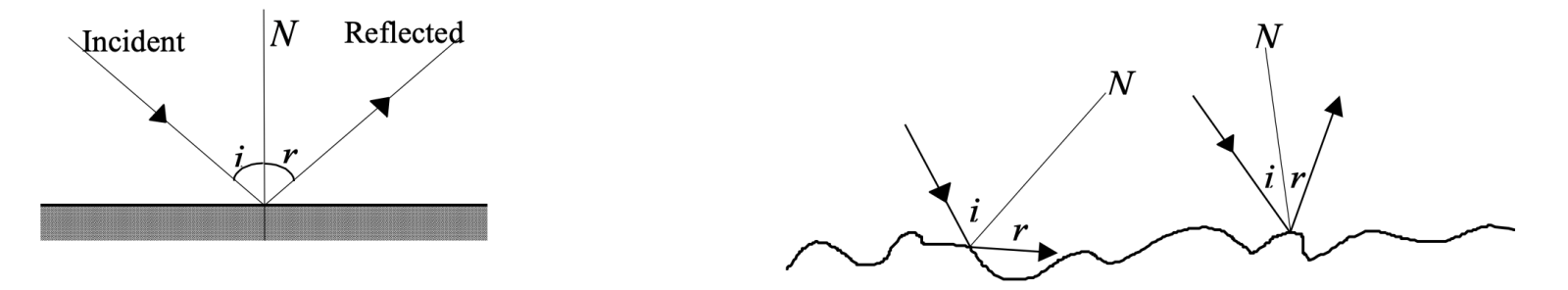
Geometric optics governs light behavior at interfaces between different media. The law of reflection states that incident and reflected ray angles equal each other (∠i = ∠r), with all rays lying in the same plane as the normal.
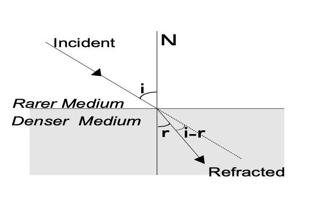
Refraction follows Snell's law: sin i/sin r = μ₂/μ₁, where μ represents refractive indices of respective media. This relationship determines light bending when transitioning between materials with different optical densities.
Critical Angle and Total Internal Reflection
Critical angle phenomena occur when light travels from denser to rarer media. The critical angle θc = sin⁻¹(μ₂/μ₁) defines the threshold beyond which total internal reflection occurs, forming the basis for optical fiber technology and various optical instruments.
Spherical Mirrors and Lens Systems
Spherical mirrors follow the mirror formula: 1/f = 1/u + 1/v, where f represents focal length, u indicates object distance, and v denotes image distance. This relationship enables precise image formation calculations for concave and convex mirrors.
Thin lens systems obey the lensmaker's formula: 1/f = (μ-1)[1/R₁ - 1/R₂], connecting focal length to refractive index μ and radii of curvature R₁ and R₂. Lens power P = 1/f (measured in diopters) quantifies focusing capability.
Magnification calculations use m = -v/u for mirrors and m = v/u for lenses, with negative values indicating inverted images. These relationships prove crucial for designing optical instruments with specific magnification requirements.
Optical Instruments and Applications
Simple Microscopes
Simple microscopes achieve magnification through single converging lenses, with magnifying power M = D/f for normal adjustment and M = (D/f) + 1 for near-point adjustment, where D represents the distance of distinct vision (typically 25 cm).
Compound Microscopes
Compound microscopes combine objective and eyepiece lenses, producing total magnification M = (v₀/u₀) × (D/fₑ), where v₀ and u₀ represent image and object distances for the objective, and fₑ indicates eyepiece focal length.
Astronomical Telescopes
Astronomical telescopes provide angular magnification M = f₀/fₑ, where f₀ and fₑ represent objective and eyepiece focal lengths respectively. This configuration enables detailed observation of distant celestial objects.
Prism Optics and Dispersion
Prisms demonstrate refraction principles through the relationship δ = i₁ + i₂ - A, where δ represents deviation angle, i₁ and i₂ indicate incident and emergent angles, and A denotes prism angle.
Minimum deviation occurs when i₁ = i₂, yielding the relationship: μ = sin[(A+δₘ)/2]/sin(A/2), connecting refractive index to measurable angles.
Dispersion phenomena arise from wavelength-dependent refractive indices, with dispersive power ω = (μᵥ - μᵣ)/(μ - 1) quantifying material's ability to separate white light into constituent colors.
Essential Optics Formulas Reference Table
| Concept | Formula | Variables & Description |
| Wave Equation | E = E₀[sin(ωt - kx + φ₀)] | E₀: amplitude, ω: angular frequency, k: wave number, φ₀: initial phase |
| Interference Amplitude | A = √(A₁² + A₂² + 2A₁A₂cos φ) | A₁,A₂: individual amplitudes, φ: phase difference |
| Young's Double Slit Phase | φ = (2π/λ)(dy/D) | λ: wavelength, d: slit separation, y: fringe position, D: screen distance |
| Fringe Width | W = λD/d | λ: wavelength, D: screen distance, d: slit separation |
| Constructive Interference | φ = 2nπ (n = 0, 1, 2...) | n: integer, φ: phase difference for bright fringes |
| Destructive Interference | φ = (2n-1)π | n: positive integer, φ: phase difference for dark fringes |
| Snell's Law | sin i/sin r = μ₂/μ₁ | i,r: incident/refracted angles, μ: refractive indices |
| Critical Angle | θc = sin⁻¹(μ₂/μ₁) | For light traveling from denser (μ₁) to rarer medium (μ₂) |
| Mirror Formula | 1/f = 1/u + 1/v | f: focal length, u: object distance, v: image distance |
| Lensmaker's Formula | 1/f = (μ-1)[1/R₁ - 1/R₂] | μ: refractive index, R₁,R₂: radii of curvature |
| Lens Power | P = 1/f (diopters) | f: focal length in meters |
| Magnification (Mirror) | m = -v/u | Negative indicates inverted image |
| Magnification (Lens) | m = v/u | v: image distance, u: object distance |
| Simple Microscope (Normal) | M = D/f | D: distance of distinct vision (25 cm) |
| Simple Microscope (Near-point) | M = (D/f) + 1 | Enhanced magnification for near-point adjustment |
| Compound Microscope | M = (v₀/u₀) × (D/fₑ) | v₀,u₀: objective distances, fₑ: eyepiece focal length |
| Telescope Magnification | M = f₀/fₑ | f₀: objective focal length, fₑ: eyepiece focal length |
| Prism Deviation | δ = i₁ + i₂ - A | i₁,i₂: incident/emergent angles, A: prism angle |
| Minimum Deviation | μ = sin[(A+δₘ)/2]/sin(A/2) | δₘ: minimum deviation angle |
| Dispersive Power | ω = (μᵥ - μᵣ)/(μ - 1) | μᵥ,μᵣ: refractive indices for violet/red light |
| Single Slit Diffraction | a sin θ = nλ (minima) | a: slit width, n: order (1,2,3...), θ: diffraction angle |
Practical Applications and Real-World Significance
This comprehensive understanding of optical principles enables applications ranging from:
- Corrective Eyewear: Using lens formulas to correct vision defects
- Camera Systems: Applying focal length and aperture relationships
- Microscopy: Achieving high magnification for scientific research
- Astronomy: Designing telescopes for celestial observation
- Fiber Optic Communications: Utilizing total internal reflection
- Spectroscopy: Using dispersion for material analysis
- Medical Imaging: Applying optical principles in diagnostic equipment
Important Note: All formulas presented follow standard physics conventions with proper sign conventions. When applying these equations, ensure consistent units and consider the geometric arrangements of optical elements for accurate results.
Reflection at Plane Surface
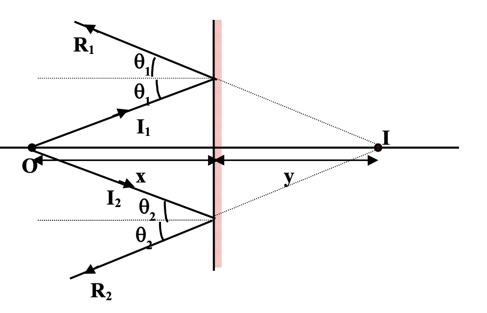
The following diagram illustrates the formation of image of a point object by a plane mirror
I1 and I2 are the two incident rays while R1 and R2 are the corresponding reflected rays. It is clear that rays R1 and R2 would not intersect in front of the mirror. However, for an observer in front of the mirror, reflected rays appear to be coming from point I and thus I is the virtual image of the of the real object O.
Using simple geometry, it can be shown that, object distance = image distance.
Other important points, which should be remembered in this context, are as follows.
- The image is laterally inverted.
- The linear magnification is unity.
- When the plane mirror is rotated through an angle θ, the reflected ray turns through double the angle, i.e. 2θ.
- When two plane mirrors are kept facing each other at an angle θ and an object is placed between them, multiple images of the object are formed as a result of successive reflection. The number of images, n, is given by,
n = ⌊ 360⁄θ − 1 ⌋; where ⌊ ⌋ denotes greatest integer function.
- Deviation caused by single reflection = 180° − 2i ( i = angle of incidence )
Reflection - at Spherical Mirrors
A spherical mirror is a reflecting surface which forms a part of a sphere. When the reflection takes place from the inner surface and outer surface is polished or silvered the mirror is known as concave mirror. Vice-versa, it is convex.
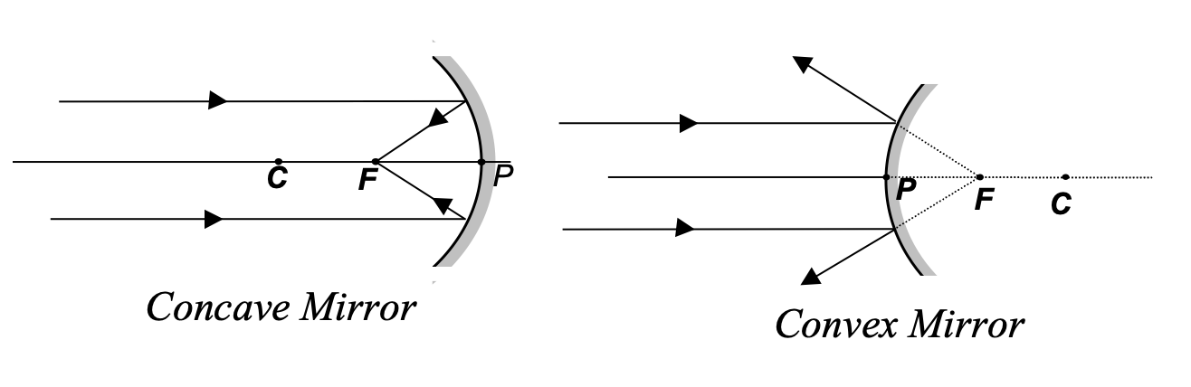
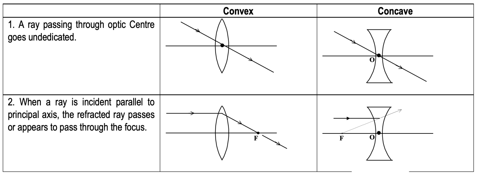
Ray Tracing
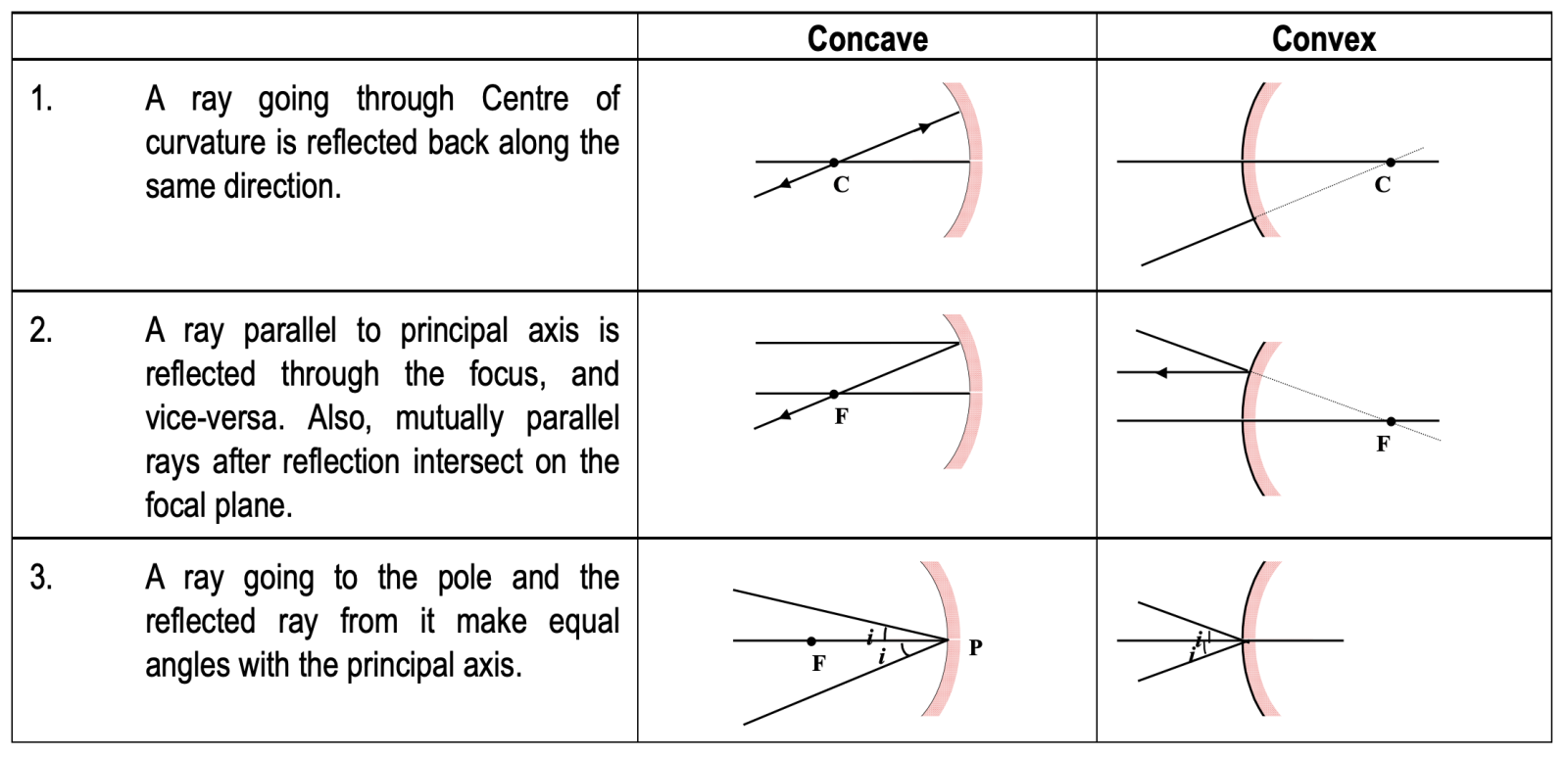
Sign convection
There are several sign-conventions. Students should try to follow any one of these. In this package, the new cartisian sign convention hasR been used wherever required.
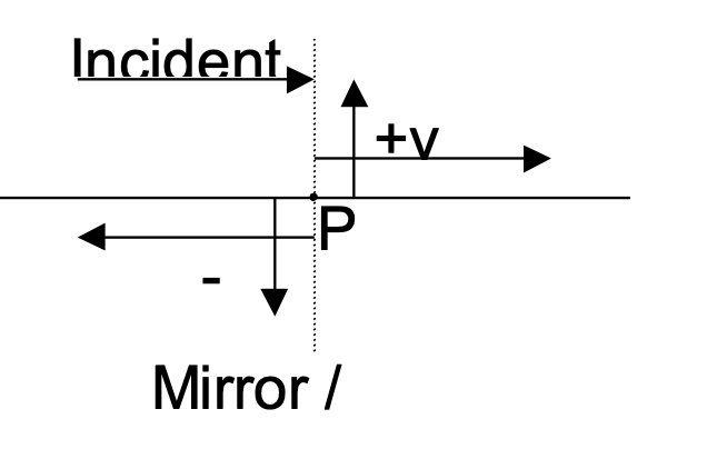
New Cartesian Sign Convention - For Mirrors And Lenses
(i) All distances are measured from the pole.
(ii) Distances measured along the direction of incident rays are taken as positive.
(iii) Distances measured along a direction opposite to the incident rays are taken as negative.
- Distances above the principal axis are positive.
- Distances below the principal axis are negative.
- Angles when measured from the normal, in anti-clockwise direction are positive, while in clockwise direction are negative.
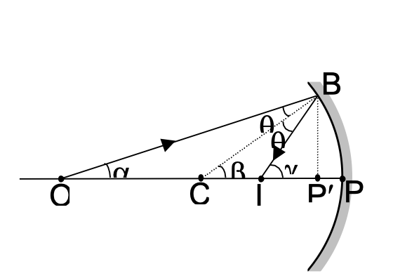
Mirror Formula
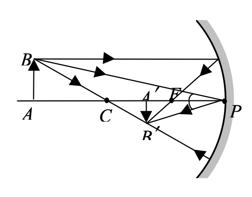
Consider the shown figure where O is a point object and I is corresponding image.
CB is normal to the mirror at B.
By laws of reflection, ∠OBC = ∠PBC = θ
α + θ = β , β + θ = γ ⇒ α + γ = 2β
For small aperture of the mirror, α, β, γ → 0
⇒ α ≈ tan α , β ≈ tan β , γ ≈ tan γ , P′ → P
⇒ tan α + tan γ = 2 tan β
⇒ BP′/OP′ + BP′/IP′ = 2 · BP′/CP′
Applying sign convention, u = −OP, v = −IP, R = −CP
⇒ −1/u + (−1/v) = −2/R
If u = ∞, 1/v = 2/R, but by definition, if u = ∞, v = f.
Hence, f = R/2 and 1/u + 1/v = 1/f
• For convex mirrors, an exactly similar formula emerges.
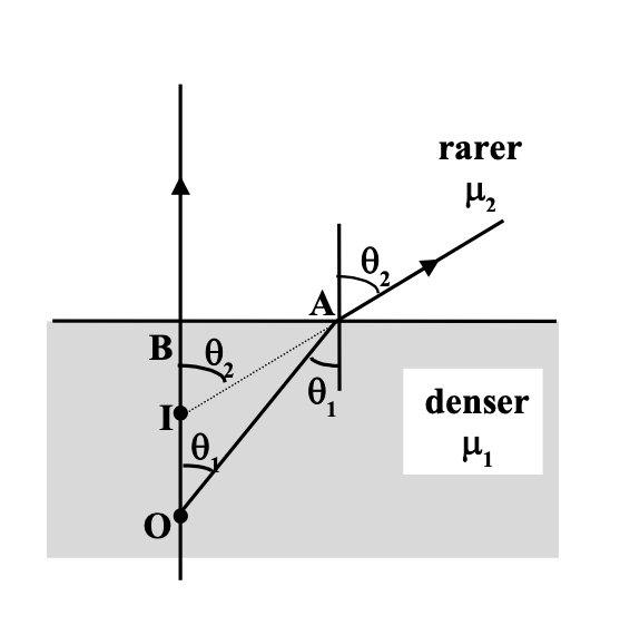
Refraction at a Plane Surface
For a given point object, the image formed by refraction at a plane surface is illustrated by the following diagrams.
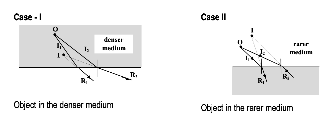
Determination of the image formed becomes simpler with nearly normal incident rays
CASE-I (Object in the denser medium)
For nearly normally incident rays, θ1 and θ2 will be very small.
1) tan θ1 ≈ sin θ1 = AB / Object distance from the refracting surface
2) sin θ2 = AB / Image distance from the refracting surface
Therefore ⇒ Image distance from the refracting surface / Object distance from the refracting surface = sin θ1 / sin θ2 = μ2 / μ1
The same result is obtained for the other case also. The image distance from the refracting surface is also known as apparent depth (or apparent height).
Apparent shift.
Apparent shift = object distance from refracting surface − image distance from refracting surface.
Δy (apparent shift) = t ( 1 − 1/μ ), where t is the object distance and μ = μ1 / μ2.
- If there are a number of slabs with different refractive indices placed between the observer and the object.
Total apparent shift = Σ Δyi.
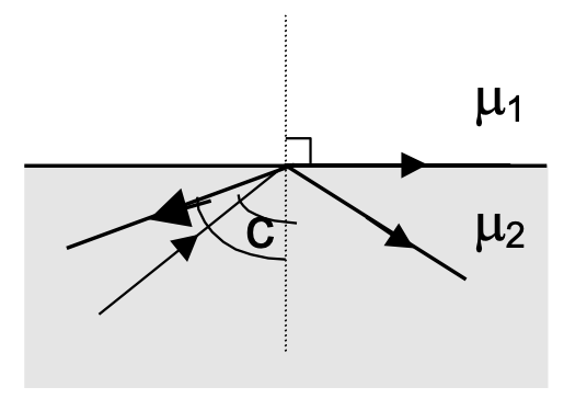
Critical Angle And Total Internal Reflection
Consider a ray of light that travels from a denser medium to a rarer medium. The angle of incidence for which the angle of refraction becomes 90° is called critical angle.
sin C / sin 90° = 2μ1 =μ1 / μ2 ⇒ sin C = 1μ2
When the angle of incidence of a ray travelling from denser to rarer medium is greater than the critical angle, no refraction occurs. The incident ray is totally reflected back into the same medium. Here the laws of reflection hold good.Some light is also reflected before the critical angle is achieved, but not totally.
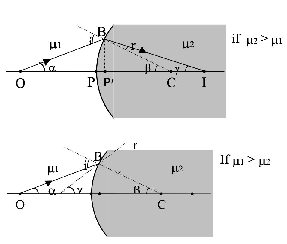
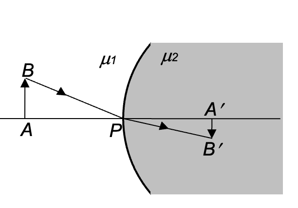
Refraction at Spherical Surfaces
Consider the point object O placed in the medium with refractive index equal to μ1.
As μ1 sin i = μ2 sin r, and for small aperture i, r → 0
→ μ1 i = μ2 r
i = α + β , β = γ + r
→ μ1(α + β) = μ2(β − γ) → μ1α + μ2γ = (μ2 − μ1)β
As aperture is small, α ≈ tan α , β ≈ tan β , γ ≈ tan γ
→ μ1 tan α + μ2 tan γ = (μ2 − μ1) tan β
→ μ1 / P'O + μ2 / P'I = μ2 - μ1 / P'C
Applying sign convention, i.e., u = −P′O, v = P′I, R = P′C
∴ For a spherical surface, μ2 / V - μ1 / u = μ2 - μ1 / R
The symbols should be carefully remembered as :
m2 - refractive index of the medium into which light rays are entering ;
m1 - refractive index of the medium from which light rays are coming.
Care should also be taken while applying the sign convention to R.
Note : A lens is converging if its focal length is positive and diverging if focal length is negative (in neo-cartesian sign convension). From this we can conclude that a convex lens need not necessarily be a converging and a concave lens diverging
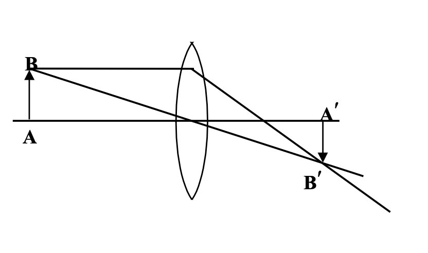
Ray tracing for lens
Magnification
In new cartesian sign convention, we define magnification in such a way that a negative sign (of m) implies inverted image and vice-versa. A real image is always inverted one and a virtual one is always erect. Keeping these points in mind and that the real object and its real image would lie on the same sides in case of mirror and on opposite sides in case of lenses, we define m as in case of reflection by spherical mirror as : m = -v/a
Lateral Magnification for Refracting Spherical Surface
m = − (A′B′) / AB.
Now, (sin i) / (sin r) = μ2 / μ1.
As i, r → 0, ⇒ (tan i) / (tan r) = μ2 / μ1.
(AB / PA) / (A′B′ / PA′) = μ2 / μ1
⇒ −(A′B′ / AB) = −(PA′ / PA) × (μ2 / μ1)
Hence, m = (v / μ2) / (u / μ1) = (μ1·v) / (μ2·u).
Magnification of a thin Lense
m = v/u = -(OA') / (AO)
POWER OF A LENS
If f is in metres then the power P=1/5 of the lens is given by, in dioptres.
Equivalent focal Length of two or more thin lenses in contact
1/F = 1/f1 + 1/f2 + …
Note: If the two thin lenses are separated by a distance d apart, F is given by
1/F = 1/f1 + 1/f2 − d/(f1 f2) so P = P1 + P2 − P1P2d
Lens with One Silvered Surface:
If the back surface of a lens is silvered and an object is placed in front of it, then the power of the silvered lens will be
P = PL + PM + PL
Where
PL = + 1/FL = 1/fL = (μ − 1) ( 1/R1 − 1/R2 )
PM = − 1/fM with FM = R2/2
So the system will behave as a curved mirror of focal length 'F' given by
F = − 1/P
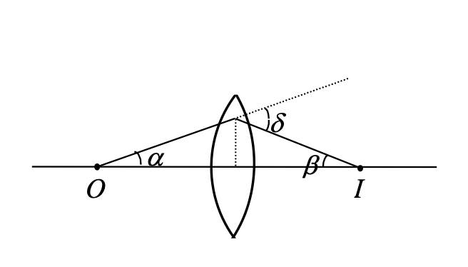
Angle of Deviation of A Ray When it Passes a Lens
O represents the object, I the image, and δ is the angle of deviation.
δ = α + β ≈ tan α + tan β
= h/(−u) + h/v = h [ 1/v − 1/u ] ⇒ δ = h/f
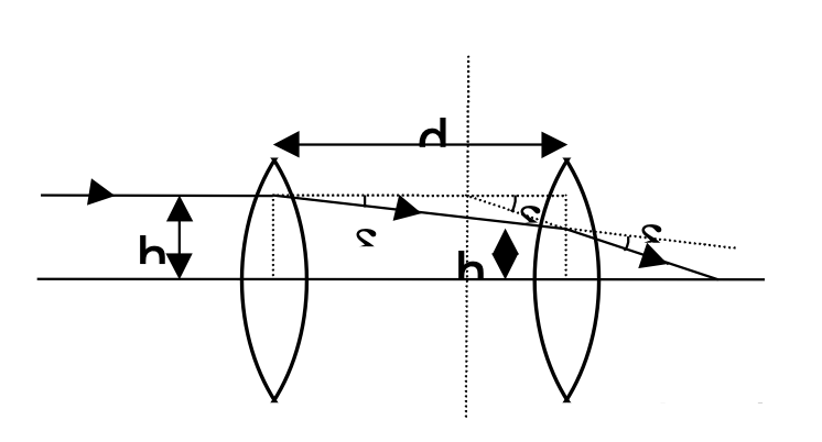
Two Thin Lenses Separated By D
δ = δ1 + δ2 ⇒ tan δ ≈ tan δ1 + tan δ2
⇒ h/F = h1/f1 + h2/f2.
But, h1 − h2 = d · tan δ1 = d · δ1 = (d · h1)/f1
⇒ h2 = h1 [ 1 − d/f1 ]
Substituting we get,
1/F = 1/f1 + 1/f2 − d/(f1 f2)
(This expression is valid for parallel rays, i.e. when object is placed at infinity.)
A more powerful form of this formula is,
P = P1 + P2 = d/μ P1P2
where P1 and P2 are optical powers of the two lenses, and m is the refractive index of the medium in between them.
Prism
Any portion of certain optical medium bounded by two inclined faces is a prism. The angle between the inclined faces is known as angle of prism.
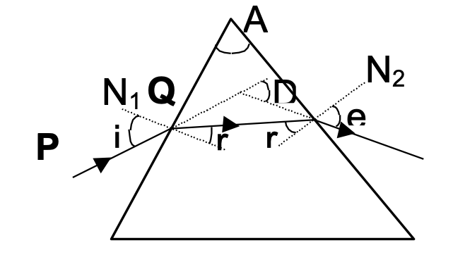
Consider the shown prism where a ray PQ is incident on face 1.
In the given figure
D = angle of deviation
i = incident angle e = emergent angle
r1 and r2 are angles of refraction.
It can be proved that,
A = r1 + r2
i + e = A + D
- Light obeys the principle of reversibility. If we send light along the emergent direction, it will emerge along the incident direction, maintaining the deviation.
- When deviation is minimum, ∠i = ∠e.
(If we assume that i ≠ e when deviation is minimum then we get two minimum angles of deviation using reversibility principle which is meaningless.)
Hence,
∠r1 = ∠r2 = ∠A / 2
⇒ μ = (sin i / sin r) = sin((A + δm)/2) / sin(A/2)
μ = sin((A + δm)/2) / sin(A/2) Prism Formula
⇒ Deviation for a small angled prism, δ = (μ − 1)A
Spherical Aberration
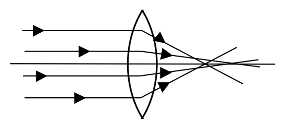
It has been assumed that the aperture of the lens or mirror is small and the light rays of interest make small angles with the principal axis. It is then possible to have a point image of a point object. However, this is only an approximation.
The rays reflect or refract from points at different distances from the principal axis. In general, they meet each other at different points. Thus, the image of a point object is a blurred surface. Such a defect is called spherical aberration.
Prevention
The magnitude of spherical aberration for a lens depends on the radii of curvature and the object distance. The spherical aberration for a particular object distance can be reduced by properly choosing the radii of curvature.
A simple method to reduce spherical aberration is to use a stop before and in front of the lens. A stop is an opaque sheet with a small circular opening in it. It only allows a narrow pencil of rays to go through the lens, hence reducing the aberration and reduces intensity of the image.
Optical Instruments
Simple Microscope
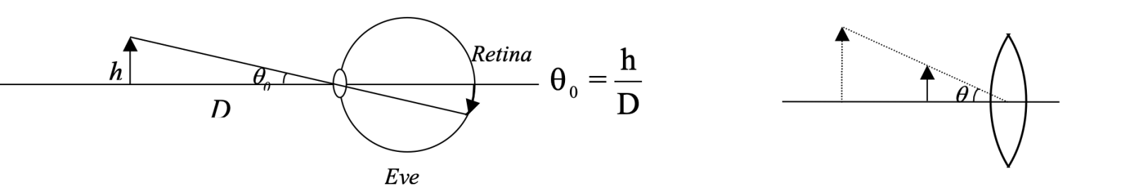
Optical instruments are used to enhance the visual angle. Magnifying power is defined as,
m = θ / θ0
where θ0 is the visual angle subtended by an object when it is seen at D, distance of distinct vision or near point, and θ is the visual angle using optical instrument.
θ0 = h / D
θ = h / u
m = (θ / θ0) = (h / u) × (D / h) ⇒ m = D / u
A simple microscope can be used in two standard adjustments, namely
(i) normal adjustment and
(ii) near-point adjustment.
In normal adjustment, the final image is seen at infinity and in near-point adjustment, the final image is seen at D, the distance of distinct vision. (D = 25 cm.)
Normal adjustment
θ0 = h/D and θ = h/f
m = θ / θ0 = (h/f) / (h/D) ⇒ m = D/f
Near-Point adjustment
Using, 1/v − 1/u = 1/f ⇒ 1/−D − 1/−u = 1/f
⇒ 1/u = [1/D + 1/u] ⇒ D/u = (1 + D/f)
m = θ/θ0 = (h/u) / (h/D) = D/u ⇒ m = 1 + D/f
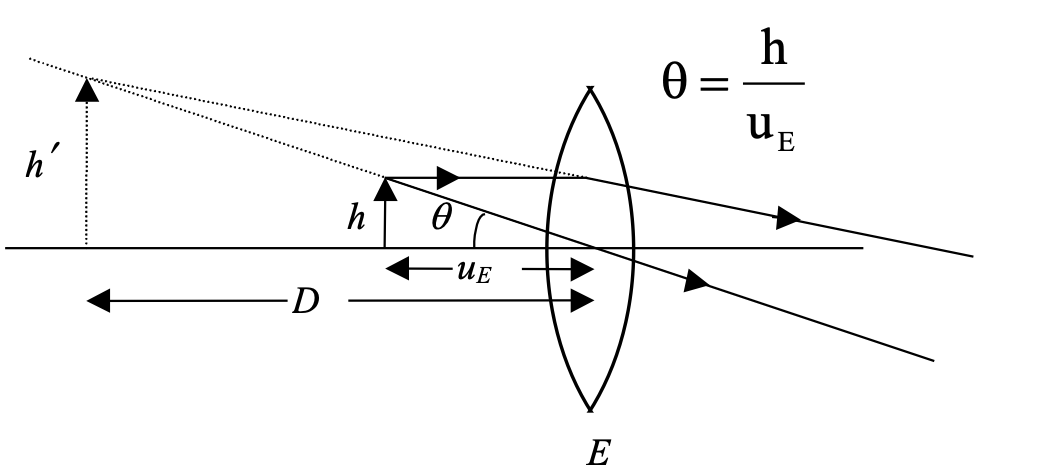
COMPOUND MICROSCOPE
θ0 = h/D , θ = h′/uE
⇒ m = θ/θ0 = (h′/uE) / (h/D) = (h′/h) [ D/uE ]
By substituting from results derived for simple microscope,
From geometry h′/h = v0/u0 ⇒ m = (v0/u0) ( D/uE )
for normal adjustment uE = fE
m = (v0/u0) [ D/fE ] for normal adjustment, and,
m = (v0/u0) [ 1 + D/fE ] for near-point adjustment
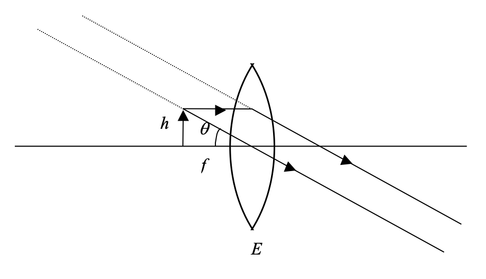
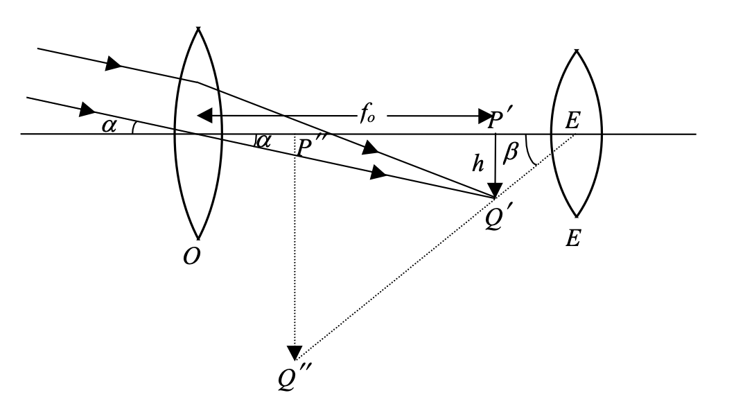
Telescope
Astronomical Telescope
m = β/α = (h/EP') / (h/fo) = fo / EP'
For normal adjustment, vE = ∞ ⇒ EP' = fE
∴ m = fo / fE and L = fo + fE
For near-pt. adjustment, vE = -D, uE = -EP'
⇒ uE = - [ (fE D) / (fE + D) ]
∴ m = (fo / fE) [ 1 + (fE / D) ] and L = fo + (fE D) / (fE + D)
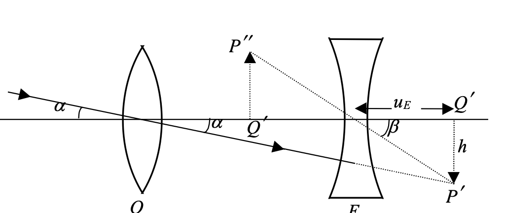
Galilean Telescope
m = β/α = (h/uE)/(h/fo) = fo/uE
For normal adjustment, uE = fE
∴ m = fo/fE and L = fo − |fE|
For near point adjustment, vE = −D
⇒ 1/uE = 1/fE − 1/D
∴ m = (fo/fE) [ (D − fE) / D ] and L = fo − uE
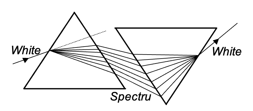
Dispersion of Light
When a ray of light passes through a prism, it splits up into rays of constituent colours or wavelengths. This phenomenon is called dispersion of light.
This phenomenon arises due to the fact that refractive index varies with wavelength. It has been observed for a prism that μ decreases with the increase of wavelength, i.e. μblue > μred.
Angular dispersion, θ = δv − δr
Dispersive power, ω = (δv − δr) / δ where δ is deviation of mean ray (yellow)
As δv = (μv − 1)A , δr = (μr − 1)A,
∴ ω = (μv − μr) / (μ − 1)
DEVIATION WITHOUT DISPERSION
This means an achromatic combination of two prisms in which net or resultant dispersion is zero and deviation is produced. For the two prisms,
(μv - μr)A + (μ' v - μ' r)A' = 0
⇒ A' = - (μv - μr)A ⁄ μ' v - μ' r and ωδ + ω'δ' = 0
where ω and ω' are the dispersive powers of the two prisms and δ and δ' their mean deviations.
Dispersion without deviation
A combination of two prisms in which deviation produced for the mean ray by the first prism is equal and opposite to that produced by the second prism is called a direct vision prism. This combination produces dispersion without deviation.
For deviation to be zero, (δ + δ′) = 0
⇒ (μ − 1)A + (μ′ − 1)A′ = 0
⇒ A′ = − (μ − 1)A
(μ′ − 1)
(−ve sign ⇒ prism A′ has to be kept inverted)
Photometry
Total radiant flux
Total energy emitted by a source per unit time (unit watt)
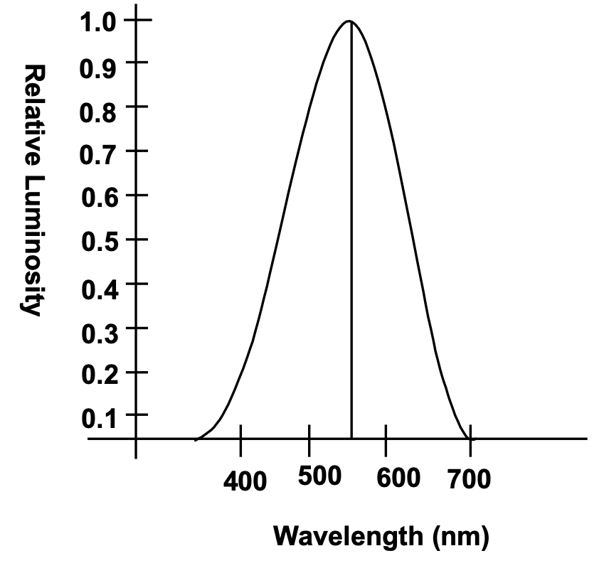
Luminosity of Radiant Flux (Brightness):
Brightness depends on the wavelength of the radiation besides depending on the total radiation flux.
Yellow light look brighter than red.
Luminous Flux (Lumen)
1 Watt source emitting monochromatic light of wavelength 555 nm emits 685 Lumens.
Relative luminosity =
Luminous flux of source of given wavelength/Luminous flux of 555nm source of same power
Luminous efficiency
Luminous efficiency = (Total luminous flux) / (Total radiant flux)
= (Luminous flux emitted) / (Power input to the source)
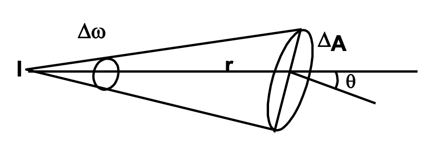
Luminous intensity
Luminous flux per unit solid angle (unit: candela)
I = dF / dΩ
If total luminous flux of the source is F, its intensity in any direction
I = F / (4π)
Illuminance
Luminous flux incident per unit area.
E = dF / dA (unit: Lumen/m² or Lux)
Inverse square law
E = (I cos θ)/r2
Δω = (ΔA cos θ)/r2
ΔF = I Δω = (I ΔA cos θ)/r2 ⇒ ΔF/ΔA = (I cos θ)/r2 = E
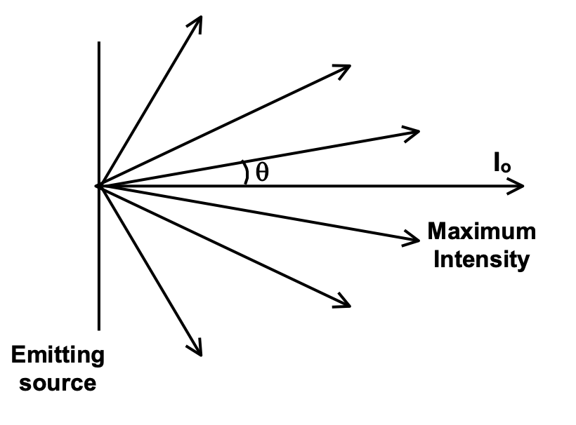
Lambert cosine law:
For extended sources, luminous intensity is different in different directions. It is maximum along the normal to the surface of the body. At an angle θ with the normal, luminous intensity
I = I0 cos θ