Force Between Magnetic Poles
The force of attraction or repulsion between two isolated magnetic poles of pole strength m₁ and m₂ separated by a distance d is:
F = (μ₀μᵣ/4π) × (m₁m₂/d²)
Where:
- μᵣ is the relative magnetic permeability of the medium
- For diamagnetic substance μᵣ < 1
- For paramagnetic substance μᵣ > 1
- For ferromagnetic substance μᵣ >> 1
- μ₀/4π = 10⁻⁷ where μ₀ is the absolute permeability of free space
Magnetic Moment
Magnetic moment, M is a vector quantity whose magnitude is M = m × ℓ where m is the pole strength and ℓ is the distance between the poles. Its direction is from south to north inside the magnet.
When Magnet is Split or Cut:
Split into n parts along length: Pole strength becomes m/n and magnetic moment becomes M/n
Cut into n parts perpendicular to length: Pole strength remains constant but magnetic moment becomes M/n due to reduction in length
Resultant Magnetic Moment
When two bar magnets are arranged at an angle θ between the like poles, the resultant magnetic moment is:
M = √(M₁² + M₂² + 2M₁M₂cosθ)
Bent Magnet Cases
- Bent into arc of circle: M' = (2M sin(θ/2))/θ where θ is in radian
- Bent at midpoint: M = M sin(θ/2)
Force Between Short Magnets
F = (μ₀/4π) × (M₁M₂/d⁴)
Diagram: Bar Magnet showing N-S poles and magnetic field lines
[Magnetic field lines emerge from North pole and enter South pole]
MAGNETIC LINES OF FORCE
The tangent drawn to the line of force at any point gives the direction of the magnetic field. An isolated North pole moves along a magnetic line of force.D
The number of lines of magnetic field passing through unit area normal to it is called magnetic induction B.
Φ = B·A = BA cosθ
where θ is the angle between the magnetic field and the normal to the given area.
Note: The flux of electric field is outward normal flux for a surface whereas magnetic flux is the flux crossing the given area.
- Force on Magnetic Pole
F = mB
- Magnetic Induction Due to Isolated Pole
B = (μ₀/4π) × (m/d²)
- Net Magnetic Induction
The net magnetic induction at a point due to configuration of poles is the vector sum:
B⃗ = B⃗₁ + B⃗₂ + B⃗₃ + ...
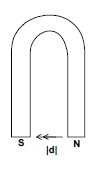
- Horse Shoe Magnet
The magnetic induction at the centre of the line joining two poles of a horse shoe magnet of pole strength m and separated by distance d is:
B = BN + BS = (μ₀/4π) × (2m/d²) + (μ₀/4π) × (2m/d²) = (μ₀/4π) × (8m/d²)
TORQUE ON A BAR MAGNET
Due to equal and opposite forces acting on the poles of a bar magnet placed in a magnetic field B, a torque acts on it about an axis passing through the centre and perpendicular to the length:
τ = MB sinθ
where θ is the angle between magnetic field B and magnetic moment M.
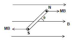
Diagram: Bar magnet in uniform magnetic field showing forces and torque
Time Period of Oscillations
Since the net force on the magnet is zero, the torque causes oscillations about equilibrium position θ = 0. For small angular displacement:
T = 2π√(I/MB)
Where I = mℓ²/12 for a thin magnet.
Note: Oscillations are simple harmonic only for small angular displacements and just periodic for large angular displacements.
Effect of Splitting Magnet
- Split into n parts parallel to length: M = M/n, I = I/n, T = T
- Cut into n parts perpendicular to length: M = M/n, I = I/n³, T = T/n
Comparing Magnetic Moments
For two magnets with time periods T₁ (like poles together) and T₂ (unlike poles together):
M₁/M₂ = (T₁² - T₂²)/(T₁² + T₂²) = (n₂² - n₁²)/(n₂² + n₁²)
MAGNETIC INDUCTION DUE TO A BAR MAGNET
- On the Axial Line
B = (μ₀/4π) × (2Md)/(d² - ℓ²)²
When ℓ << d:
B = (μ₀/4π) × (2M/d³)
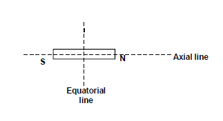
- On the Equatorial Line
B = (μ₀/4π) × (M)/((d² + ℓ²/4)^(3/2))
When ℓ << d:
B = (μ₀/4π) × (M/d³)
Diagram: Bar magnet showing axial and equatorial lines
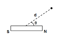
- At Any Point
Magnetic induction due to short bar magnet at distance d from centre making angle θ with S-N axis:
B = (μ₀/4π) × (M/d³) × √(1 + 3cos²θ)
- Magnetic Potential
Work done in bringing a unit north pole from infinity to a point in magnetic field:
V = (μ₀/4π) × (M cosθ/d²)
Note: Magnetic potential at any point on equatorial line of bar magnet is zero.
WORK DONE IN ROTATING A BAR MAGNET
Work done in rotating a bar magnet against the torque:
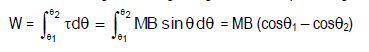
- Potential Energy
U = -M⃗·B⃗ = -MB cosθ
As work done equals change in potential energy: W = U₂ - U₁ = MB(cosθ₁ - cosθ₂)
TERRESTRIAL MAGNETISM
Earth can be considered as a bar magnet with south pole towards geographic north and north pole towards geographic south.
- Meridian: Plane passing through point and corresponding poles (magnetic or geographic)
- Declination: Angle between magnetic meridian and geographic meridian (max 17° at equator)
- Dip/Inclination: Angle made by Earth's magnetic field with horizontal (0° at magnetic equator, 90° at magnetic pole)
Components of Earth's Magnetic Field
BH = B cosδ (Horizontal component)
BV = B sinδ (Vertical component)
Where δ is the dip angle.
B = √(BH² + BV²)
tanδ = BV/BH
Apparent Dip
If plane is at angle θ with magnetic meridian, apparent dip δ₁ is:
tanδ₁ = tanδ/cosθ
For two mutually perpendicular directions:
cot²δ = cot²δ₁ + cot²δ₂
BAR MAGNET IN EARTH'S MAGNETIC FIELD
When bar magnet is kept in Earth's magnetic field, resultant field is vector sum of both fields. A null or neutral point is where resultant magnetic field parallel to Earth's surface is zero.
- North pole towards geographic north: Null points on equatorial line
- North pole towards geographic south: Null points on axial line
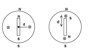
Diagram: Bar magnet in Earth's field showing null points
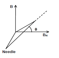
Deflection of Magnetic Needle
When magnetic needle is in two perpendicular magnetic fields BH and B:
tanθ = B/BH
where θ is deflection angle.
TANGENT GALVANOMETER
A coil of n turns carrying current i produces magnetic field along axis:
B = (μ₀ni)/(2r) where r is radius of coil.
If field is horizontal and perpendicular to BH:
tanθ = B/BH
i = (2rBH)/(μ₀n) × tanθ = k tanθ
k is called reduction factor of galvanometer.
PROPERTIES OF MAGNETIC MATERIALS
- Magnetizing Force (H): Force that induces magnetism in material
- Intensity of Magnetization (I): Magnetic moment per unit volume or pole strength per unit area
I = M/V = m/A
- Relations
B = μH = μ₀μᵣH = μ₀(H + I)
- Magnetic susceptibility:
χ = I/H
μᵣ = 1 + χ
- Hysteresis Loop
Plot of intensity of magnetization against magnetizing field.
- Retentivity: Residual magnetism when external field is zero
- Coercivity: Capacity to retain magnetism despite demagnetizing process
- Area of loop: Represents work done or energy loss
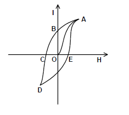
Diagram: Hysteresis loop showing retentivity and coercivity
PARA, DIA AND FERROMAGNETIC MATERIALS
Diamagnetic materials are repelled by magnets. Relative permeability is positive and less than one. Magnetic susceptibility is negative and small. Diamagnetic property is shown by materials with paired electrons and is independent of temperature. Ex: Bismuth, Zinc, Copper, Silver, water, nitrogen and hydrogen.
Paramagnetic materials are feebly attracted by magnets. They get magnetized along the direction of the magnetic field. Relative permeability is more than one and positive. Magnetic susceptibility is small and positive.
![]()
which is known as curie's law and C is curie's constant. Materials with unpaired electrons in their valence orbits exhibit this property.
- Example: Aluminium, Sodium, Platinum, Manganese and oxygen,
Ferromagnetic materials are strongly attracted by magnets. Relative permeability is very large and magnetic susceptibility is very high and positive. Magnetic susceptibility is constant upto a certain temperature above which it varies with temperature according to the equation.
![]()
Where K and TC are constants and TC is called Curie temperature above which a ferromagnetic material becomes paramagnetic.
Ferromagnetism is due to the existence of magnetic domains.
Example: Iron, Nickel, Cobalt and Gadolinium.
MAGNETIC FIELD DUE TO CURRENT
Magnetic field due to current can be calculated using:
- Biot-Savart's Law (general cases)
- Ampere's Circuital Law (symmetrical cases)
Biot-Savart's Law
To get the magnetic field at a point using Biot-Savart's law, we need to understand the term current-element. Current element is the product of current and length of infinitesimal segment of current carrying wire. The current element is taken as a vector quantity. Its direction is same as the direction of current.
dB⃗ = (μ₀/4π) × (Idl⃗ × r⃗)/r³
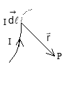
For entire wire segment:
B⃗ = (μ₀I/4π) ∫ (dl⃗ × r⃗)/r³
Here mo is proportionality constant, called permeability. In SI units the value of mo/4p is equal to 10-7 Tesla-meter/ampere. The SI units of magnetic fields are Tesla, weber/m2.
In the above expression limits of the integral depend on the shape and size of the current carrying wire.
Magnetic Field Due to Different Current Systems
1. Straight Wire
B = (μ₀I/4πR)(sinα - sinβ)
For infinitely long wire (α = π/2, β = -π/2):
B = μ₀I/(2πR)
2. Arc of Circle
B = (μ₀I/4πR) × θ
For complete circle (θ = 2π):
B = μ₀I/(2R)
3. On Axis of Circular Loop
B = (μ₀IR²)/(2(R² + x²)^(3/2))
4. Solenoid
At centre:
Bcentre = (μ₀nI/2)(sinα - sinβ)
For long solenoid (α = 90°, β = -90°):
Bcentre = μ₀nI
At ends:
Bends = μ₀nI/2
Illustration: A charge q moves in circular path of radius r with speed v. Calculate magnetic field at centre.
Solution:
Equivalent current: I = qv/(2πr)
Magnetic field: B = μ₀I/(2r) = μ₀qv/(4πr²)
Magnetic Moment
Magnetic field at any point on the axis of the loop is along the axis only. We have already calculated the direction of magnetic field using BIOT-SAVART Law. We can also calculate the direction of magnetic field directly using right-handed nut-bolt system. "Take a nut fitted with a bolt and hold it in such a way that plane of the nut should be parallel to the plane of the loop. Now rotate the bolt in same sense as the sense of current in the loop. The bolt will move in the direction of magnetic field."
A closed loop behaves like a magnetic dipole, its magnetic moment is given by the expression M = NIA Here N = no of turns
A= area vector and its direction can be given by right handed nut-bolt system.
Gauss's Law of Magnetism
∮ B⃗·ds⃗ = 0
Net flux of B through any closed surface is zero.
Ampere's Law: ∮ B⃗·dl⃗ = μ₀I
Line integral of B around closed path equals μ₀ times total current through surface bounded by path.
MOTION OF A CHARGED PARTICLE IN A MAGNETIC FIELD
In previous chapter we studied about the source of magnetic field. In this chapter we shall study the effect of magnetic field on a moving charge and on current carrying wire.
In magnetic field force experienced by a charged particle is given by the expression:
Fm = q(v × B)
Here,
- v = velocity of the particle
- B = magnetic field
On the basis of above expression, we can draw the following conclusions:
- Stationary charge (i.e. v = 0) experiences no magnetic force.
- If v is parallel or anti parallel to B then the charge particle experiences no magnetic force.
- Magnetic force is always perpendicular to both the v and B.
- As magnetic force is always perpendicular to the velocity (→v), the magnetic force does not deliver power to the charged particle.
- As magnetic force is always perpendicular to →v, this force will compel the charge particle to move on a circular path.
-
On the basis of Expression for Magnetic Force →F = q(→v × →B) The maximum value of the magnetic force is F = qvB which occurs when the charge is projected perpendicular to the magnetic field. This makes the path of the charged particle purely circular (in uniform →B), and magnetic force provides the necessary centripetal force.
- Radius of the Circular Path
If radius of the circular path is R:
mv2 R = qvB , where m = mass of the particle.
Therefore, R = mvqB
- Time to Complete One Revolution
T = 2πRv = 2πmqB
- Helical Path of a Charged Particle
If the charged particle is projected neither parallel nor perpendicular to the field, its velocity →v can be resolved into two components: one along →B (v_{||}) and the other perpendicular to →B (v_{\perp}).
Experiences a magnetic force and tends to move on a circular path due to v⊥.
Experiences no force and tends to move straight along the field due to v∥.
Illustration: A uniform magnetic field of 30 mT exists in the +X direction. A particle of charge +e and mass 1.67 × 10⁻²⁷ kg is projected through the field in the +Y direction with a speed of 4.8 × 10⁶ m/s.
- (a) Find the force on the charged particle in magnitude and direction.
- (b) Find the force if the particle were negatively charged.
- (c) Describe the nature of path followed by the particle in both the cases.
Solution:
(a)F = qvB sin θ
Calculation:
F = (1.6 × 10-19) × (4.8 × 106) × (30 × 10-3) × sin 90o =2.304 × 10⁻¹⁵ N
The direction of the force is in the (-z) direction.
(b) If the particle were negatively charged, the magnitude of the force would be the same, but the direction would be along the (+z) direction.
(c) As v ⊥ B, the path described is a circle.
R = mv qB
Substituting values: R = (1.67 × 10-27) × (4.8 × 106) (1.6 × 10-19) × (30 × 10-3) = 1.67 m
Lorentz Magnetic Force
dF⃗ = I(dl⃗ × B⃗)
Net force on wire:
F⃗ = I ∫ (dl⃗ × B⃗)
Note: No net force on current carrying loop in uniform magnetic field.
Fleming's Left Hand Rule
Index finger → Magnetic field direction
Middle finger → Current direction
Thumb → Force direction
Force Between Parallel Conductors
Magnetic field at distance r from wire carrying current I₁:
B = μ₀I₁/(2πr)
Force per unit length on second wire:
F/l = μ₀I₁I₂/(2πr)
Note: Wires carrying current in same direction attract each other.
Torque on Current Loop
Current carrying loop in uniform magnetic field experiences torque:
τ⃗ = M⃗ × B⃗
where M⃗ = IA⃗ is magnetic moment of loop.
MOVING COIL GALVANOMETER
Coil of N turns, area A carrying current I in magnetic field B experiences torque:
τ = NIAB sinθ
For radial field (θ = 90°):
τ = NIAB
Balanced by restoring couple:
NIAB = Cφ
I = (C/NAB)φ = kφ
where k is galvanometer constant.
Current Sensitivity
S = φ/I = NAB/C
AMMETER
Galvanometer with small parallel resistance (shunt) for measuring current.
Shunt Resistance
To increase range from ig to i:
S = G/(n-1) = Gig/(i-ig)
where n = i/ig is multiplication factor.
Fractional Error
If ammeter has resistance r in circuit with external resistance R:
Fractional error = r/(R+r)
Ideal Ammeter: Should have zero resistance
VOLTMETER
Galvanometer with high series resistance for measuring potential difference.
Series Resistance
To convert galvanometer (resistance G, max current Ig) to voltmeter of range V:
R = V/Ig - G
Fractional Error
If voltmeter has resistance r measuring voltage across resistance R:
Fractional error = R/(R+r)
Ideal Voltmeter: Should have infinite resistance
EXERCISES
Exercise 1:
-
Solenoid of infinite length, 0.1 A per turn, 2000 turns. Find magnetic field inside. Answer: 8×10⁻⁵ T
-
Semi-circular loop on X-Z plane, semi-infinite parts on X-Y plane. Find B at origin. Answer: μ₀I/(4A)
-
Circular loop, radius 12cm, B = 0.5×10⁻⁴ T at centre. Find B at 5cm on axis. Answer: 3.9×10⁻⁵ T
-
Is magnetic field of current loop uniform? Answer: No
Exercise 2:
- Electron with velocity âk in magnetic field b î + ĉ ĵ. Find magnetic force. Answer: ea(bĵ - cî)
- Can charged particle from field-free region complete closed path in magnetic field? Answer: No
- Smallest B at equator for proton (speed 10⁷ m/s) to circulate around Earth? Answer: 1.6×10⁻⁸ T
FORMULAE AND CONCEPTS AT A GLANCE
Key Formulae:
1. Magnetic dipole moment: M⃗ = md⃗ = IA⃗
2. Magnetic field: B = (μ₀/4π) × (m/d²)
3. Magnetic field due to current: B = (μ₀I/4π) × (dl⃗ × r⃗)/r²
4. Tangent law: tan θ = H/BH
5. Permeability: μᵣ = 1 + χm
6. Force on conductor: F⃗ = I(dl⃗ × B⃗)
7. Force between parallel conductors: F = (μ₀I₁I₂l)/(2πr)
8. Lorentz force: F⃗m = q(v⃗ × B⃗)
© FIITJEE Group - Complete Study Material on Magnetism and Magnetic Effects of Current